 Visual Paradigm Desktop |
  Visual Paradigm Online


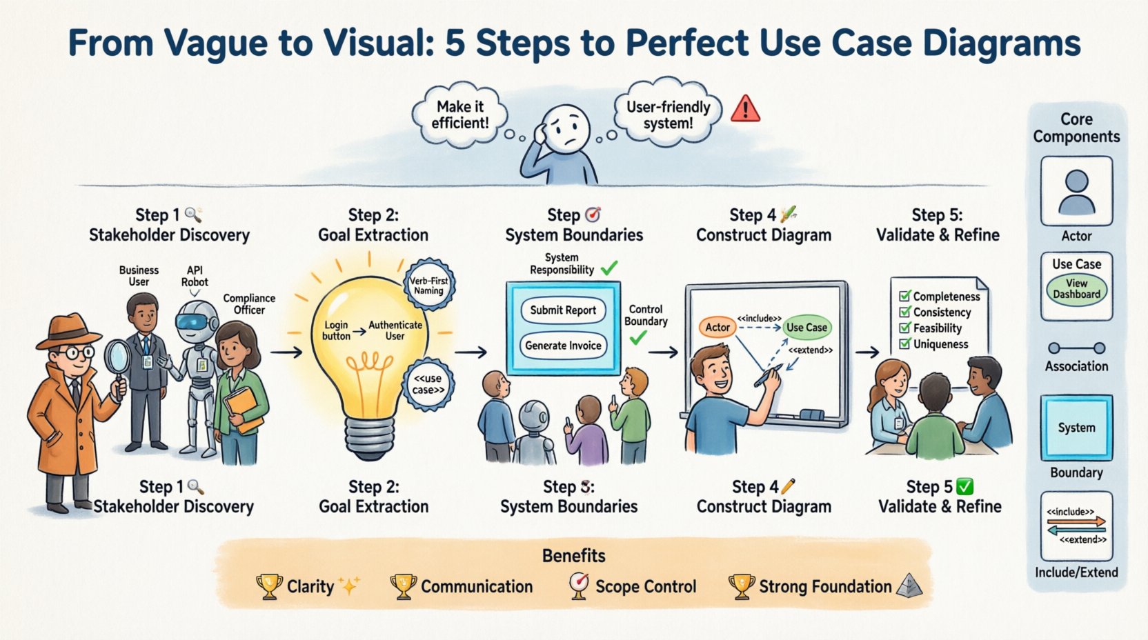
Project success often hinges on clarity. Yet, stakeholders frequently provide requirements that are broad, ambiguous, or contradictory. 🤔 When the initial input lacks specificity, the risk of building the wrong system increases significantly. This guide provides a structured approach to converting imprecise input into actionable, visual models.
Using Use Case Diagrams allows teams to visualize interactions between users and systems. It transforms abstract ideas into concrete specifications. This process reduces miscommunication and sets a solid foundation for development. We will explore the methodology to ensure your models are accurate and useful.
Vague requirements create a gap between expectation and delivery. Without clear definitions, developers make assumptions. These assumptions often lead to rework. Stakeholders feel the final product does not match their vision. Engineers waste time fixing logic errors that could have been caught earlier.
Here are common symptoms of vague requirements:
Addressing these issues early saves resources. Use Case Diagrams serve as a communication bridge. They force the team to define exactly who does what. This clarity prevents costly changes later in the lifecycle.
Before translating requirements, you must understand the building blocks. A diagram consists of specific elements. Each element represents a distinct part of the system logic. Confusion over these terms leads to poor modeling.
The following table outlines the essential components:
| Component | Description | Role in Modeling |
|---|---|---|
| Actor | A role played by a user or external system. | Identifies who initiates actions. |
| Use Case | A specific function or goal the system performs. | Defines what the system does. |
| Association | A line connecting an actor to a use case. | Shows communication paths. |
| System Boundary | A box containing all use cases. | Defines scope and limits. |
| Include/Extend | Relationships between use cases. | Manages optional or shared logic. |
Understanding these terms is critical. If you cannot define an actor, you cannot model their interaction. If you cannot define a boundary, the scope is undefined. Precision here dictates the quality of the final model.
The first step involves identifying every potential actor. Stakeholders are not just end-users. They include administrators, external systems, and third-party services. Missing an actor means missing a requirement.
To identify actors effectively:
Classify actors into categories to maintain order:
Documenting this list creates a checklist. You can verify later if every actor has a corresponding set of use cases. This prevents scope creep where external dependencies are forgotten.
Once actors are known, determine their goals. A use case is essentially a goal achieved by an actor using the system. Vague requirements often state features instead of goals. You must translate features into goals.
Example of translation:
When defining use cases, follow these rules:
This step requires careful analysis of the vague input. You must ask “Why does the actor want this?” The answer is the use case name. This shifts the focus from implementation details to functional intent.
Boundaries define what the system includes and what it excludes. This is often the most difficult part of modeling vague requirements. You must decide what falls inside the box.
Consider the following criteria for boundary definition:
Anything outside the boundary is a secondary actor or an external dependency. Anything inside is a use case. This distinction is vital for development teams. It clarifies what needs to be coded versus what is assumed to exist.
Common mistakes include:
Draw a clear rectangle around your use cases. Label this box with the system name. Ensure all primary actors are outside this box. This visual cue reinforces the scope immediately.
Now, draw the connections. Associations link actors to use cases. They represent the flow of communication. A solid line indicates a direct relationship.
Follow these construction steps:
Complex systems may require relationship types beyond simple associations. Use the following table to guide relationship selection:
| Relationship | Symbol | Usage Context |
|---|---|---|
| Include | Arrow with <<include>> | Used when a use case always requires another to complete. |
| Extend | Arrow with <<extend>> | Used for optional behavior that happens under specific conditions. |
| Generalization | Triangle Arrow | Used for inheritance between actors or use cases. |
Do not overcomplicate the diagram. A clean diagram is better than a cluttered one. If a relationship is complex, document it in the text description instead of the visual model. The goal is clarity, not complexity.
A draft diagram is rarely perfect. Validation ensures the model matches reality. Review the diagram with stakeholders. Ask them to verify the flows.
Validation checklist:
During this phase, you may find that vague requirements were hiding edge cases. Stakeholders might realize a feature is optional or that a specific role was missing. Update the diagram accordingly. This iterative process is normal.
Refinement also involves checking the granularity. If a use case is too broad, break it down. If it is too narrow, merge it. Aim for a level of detail that is actionable for developers but high enough for stakeholders to understand.
Even experienced modelers make mistakes. Recognizing these pitfalls helps you avoid them. Here are common errors to watch for:
| Pitfall | Consequence | Correction |
|---|---|---|
| Designing the UI | Focuses on screens instead of functions. | Focus on goals, not interfaces. |
| Too Many Actors | Diagram becomes unreadable. | Group roles or generalize actors. |
| Internal Steps | Modeling backend logic as use cases. | Keep use cases at the user goal level. |
| Missing External Systems | Assumes data exists when it does not. | Identify all data sources as actors. |
Avoid the trap of modeling internal processes. Use Case Diagrams are external views. They show what the user sees, not how the code works. Internal logic belongs in sequence diagrams or process flows.
The diagram is a summary. It needs support from detailed text. A use case description elaborates on the specific steps involved. This ensures the diagram is not just a picture but a specification.
For each use case, document:
This documentation turns the visual model into a contract. Developers use it to write code. Testers use it to create test cases. Stakeholders use it to verify requirements. The diagram anchors this entire ecosystem.
Translating vague requirements into precise diagrams offers tangible value. It aligns the team. It reduces risk. It saves money.
Key takeaways include:
Invest time in this modeling phase. The effort spent now prevents confusion later. A precise Use Case Diagram is a sign of a mature engineering process. It demonstrates a commitment to quality and precision. By following these steps, you ensure your requirements are not just written, but understood.
Start with the actors. Define the goals. Draw the boundaries. Validate the model. This path leads to successful system delivery. 🚀