 Visual Paradigm Desktop |
  Visual Paradigm Online


Every product manager and stakeholder knows the feeling. A project starts with a clear vision, a defined set of features, and a realistic timeline. Months later, the roadmap is cluttered with new requests, the deadline has slipped, and the team is exhausted. This phenomenon is known as scope creep. It is the silent killer of software projects, eroding budgets and delaying delivery without adding proportional value.
Preventing this drift requires more than just saying no. It requires a structural approach to defining what the system actually does and, more importantly, what it does not do. This is where the use case diagram becomes an indispensable tool for Product Owners. It serves as a visual contract between the development team and the business, establishing clear boundaries for the system under construction.
This guide explores how to leverage use case diagrams to maintain control over project scope, align stakeholder expectations, and deliver value consistently.
Scope creep is not merely about adding features. It is about uncontrolled expansion of project objectives without adjustments to time, cost, or resources. It often manifests in subtle ways: a “quick fix” that becomes a permanent feature, a stakeholder request that bypasses the standard review process, or a misunderstanding of what constitutes a completed requirement.
When scope expands unchecked, several negative outcomes emerge:
Product Owners act as the gatekeepers of value. To do this effectively, they need a mechanism to visualize the system’s limits. A use case diagram provides this mechanism by mapping the interactions between users and the system.
The Product Owner holds the responsibility of maximizing the value of the product resulting from the work of the Development Team. However, value cannot be maximized if the boundaries of the work are blurred. Defining clear boundaries involves two distinct activities: articulation and protection.
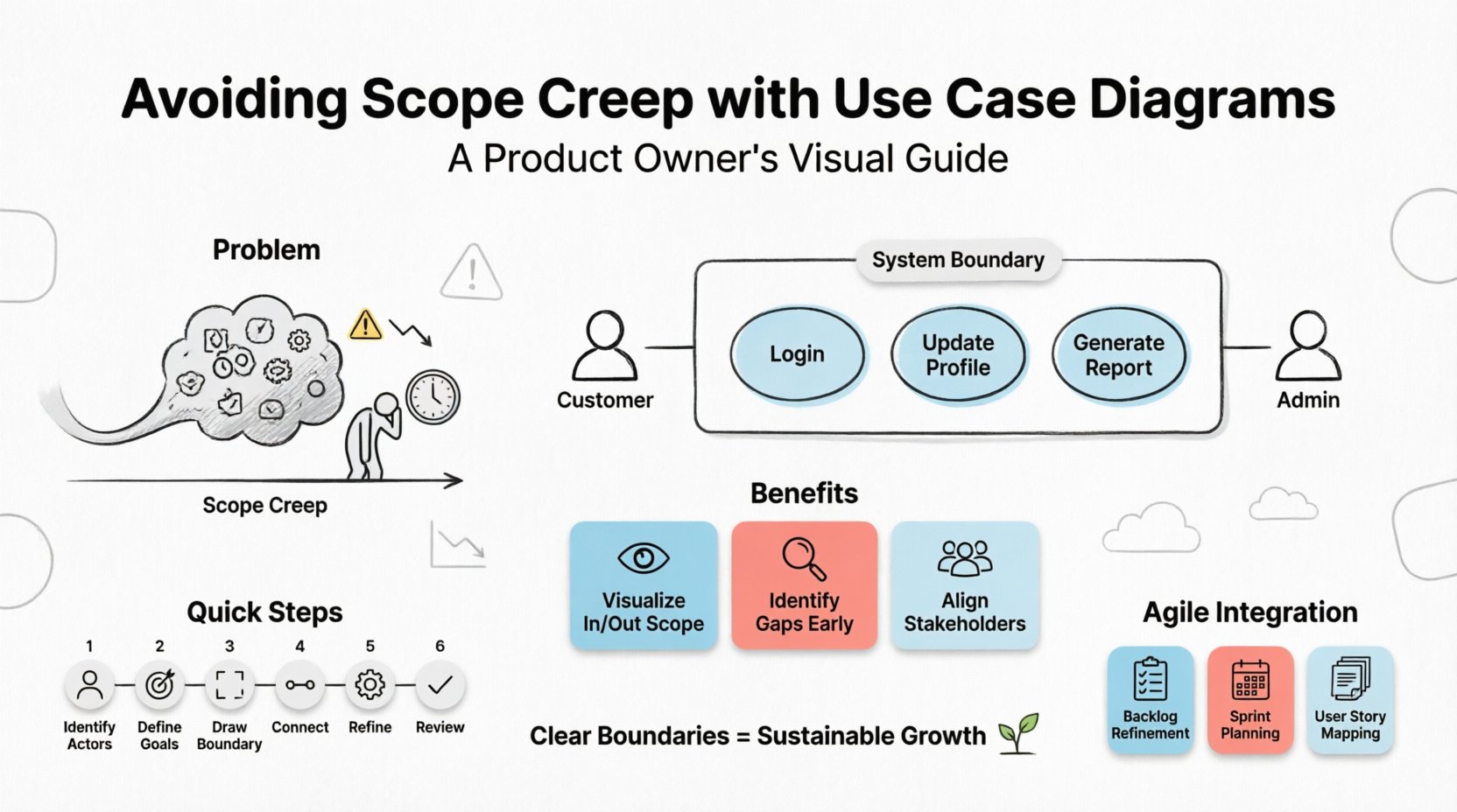
Articulation means communicating exactly what the system will achieve. This is where the use case diagram shines. It translates abstract business goals into concrete system interactions. Instead of saying “the system needs to handle user data,” the diagram specifies “User logs in,” “User updates profile,” and “System validates credentials.”
Protection means resisting the urge to add functionality that falls outside the agreed-upon model. When a new request comes in, the Product Owner can refer to the diagram. If the request does not fit an existing actor or use case, it is flagged for review. It is not automatically added to the current sprint.
To use a diagram effectively, one must understand its components. A use case diagram is a visual representation of the functional requirements of a system. It focuses on the “who” and the “what,” rather than the “how.” This abstraction is key to preventing scope creep, as it keeps the focus on user goals rather than implementation details.
Key elements include:
By strictly adhering to these components, Product Owners ensure that every feature requested has a place in the model. If a feature cannot be mapped to an actor or a use case, it raises a red flag that requires discussion.
The primary power of the use case diagram lies in its ability to visualize the system boundary. This boundary is the line in the sand. Anything inside is in scope. Anything outside is out of scope.
Visualizing the “In” and “Out”
When stakeholders request a feature, the Product Owner can point to the diagram. “This request involves the Inventory System. The diagram shows the Inventory System is external to our current scope.” This visual evidence makes the conversation about scope management objective rather than subjective.
Identifying Gaps Early
During the creation of the diagram, the team reviews all potential interactions. This review often reveals missing requirements before coding begins. If a critical user action is not captured in the diagram, it is identified as a gap. Addressing gaps during the modeling phase is significantly cheaper than fixing them after development.
Stakeholder Alignment
Diagrams provide a common language. Developers, business analysts, and stakeholders can all look at the same diagram and understand the agreed-upon interactions. This reduces the risk of misinterpretation, which is a common driver of scope creep.
Creating a useful diagram requires a disciplined approach. It is not enough to draw shapes; the content must be precise.
Even with the best intentions, diagrams can become part of the problem if created poorly. Product Owners should watch out for these common pitfalls.
Agile methodologies emphasize iterative development and adaptability. Some may argue that static diagrams contradict this fluidity. However, a well-maintained use case diagram supports agility by providing a stable reference point amidst change.
Backlog Refinement
During backlog refinement sessions, the Product Owner can refer to the diagram to ensure new user stories align with the defined system boundaries. If a story does not map to an existing use case, it triggers a discussion on whether it belongs in the current scope or a future release.
Teams can use the diagram to understand the context of their work. Knowing the actor and the goal helps developers build better tests and edge cases. It ensures that the sprint goal contributes to the overall system objective.
Use cases can be broken down into user stories. The diagram acts as the backbone. Each use case can be decomposed into multiple stories. This hierarchy helps in prioritizing features. High-value use cases get prioritized, while low-value extensions are deferred.
A diagram that is not updated is a liability. It becomes a source of confusion rather than clarity. Product Owners must treat the diagram as a living document.
Version Control
Keep track of changes to the diagram. If a significant change occurs in the system architecture or scope, create a new version of the diagram. This allows the team to trace how the requirements have evolved over time.
Change Requests
When a major change request is submitted, it should be evaluated against the current diagram. Does this change require a new actor? Does it require a new use case? Does it extend an existing one? The answer determines the impact on the timeline and budget.
Retrospectives
Use the diagram during retrospectives. Did the team miss any interactions? Were there any scope creep incidents that the diagram failed to prevent? This feedback loop helps refine the modeling process for future iterations.
| Indicator of Scope Creep | Prevention Strategy using Use Case Diagrams |
|---|---|
| Stakeholders request features during development. | Refer to the diagram to show the feature is outside the boundary. Move to backlog for future consideration. |
| Requirements change frequently. | Use the diagram as a baseline. Any change must be a formal update to the model, not just a verbal request. |
| Team adds “small” features without approval. | Review the diagram weekly. Ensure every implemented feature maps to a use case. If not, initiate a review. |
| Unclear responsibilities between teams. | Clearly define external actors. Distinguish between internal use cases and external system interactions. |
| Timeline slips due to hidden complexity. | Use the diagram to identify complex relationships (Include/Extend). Estimate effort based on the number of interactions, not just features. |
| Element | Description | Role in Scope Management |
|---|---|---|
| Actor | External entity interacting with the system. | Defines who is responsible for initiating actions. Prevents assuming internal capabilities for external needs. |
| Use Case | A specific function or goal within the system. | Defines the scope of work. If it is not a use case, it is not in scope. |
| System Boundary | The box enclosing the use cases. | Visually separates the system from the environment. The most critical tool for saying “no.” |
| Association | Line connecting Actor to Use Case. | Clarifies responsibility. Shows exactly who does what. |
| Include/Extend | Relationships between use cases. | Manages complexity. Prevents duplication of requirements across different use cases. |
Beyond the technical aspects, use case diagrams have a psychological impact on the team and stakeholders. Ambiguity breeds anxiety. When requirements are vague, stakeholders feel the need to add more to “cover their bases.” When requirements are clear, confidence grows.
A clear diagram reduces the cognitive load on the Product Owner. Instead of remembering every verbal request, they have a visual reference. This allows them to focus on value prioritization rather than administrative defense. It also empowers the development team. When developers know the boundaries, they can make technical decisions with confidence, knowing they are not inadvertently expanding the scope.
Furthermore, it fosters trust. When stakeholders see that the Product Owner is protecting the team from scope creep, they respect the process. They understand that the timeline is realistic because the scope is defined. This trust is essential for long-term collaboration.
Scope creep is a natural tendency in complex projects. It is not a sign of failure, but a signal that boundaries need reinforcement. The use case diagram provides the structure needed to reinforce those boundaries without stifling innovation.
By defining actors, use cases, and relationships clearly, Product Owners create a framework for sustainable growth. This framework allows the product to evolve in a controlled manner. It ensures that every new feature adds value and aligns with the core vision of the system.
Investing time in modeling is not a waste of time. It is an investment in clarity. It is an investment in delivery. It is an investment in the health of the team. When the boundaries are clear, the path to success becomes visible. The Product Owner leads the way, ensuring that the product delivers on its promises without losing its way.
Start drawing. Start defining. Start protecting your scope.