 Visual Paradigm Desktop |
  Visual Paradigm Online


Communication lies at the heart of product development. Whether you are defining scope, aligning stakeholders, or guiding engineering teams, clarity is paramount. Visual models serve as a universal language, bridging the gap between technical constraints and business goals. Among these tools, the Use Case Diagram stands out as a foundational instrument for mapping system functionality from a user perspective. For product managers, understanding these diagrams is not merely about technical literacy; it is about precision in requirements and scope management.
This guide breaks down the symbols, relationships, and implications of Use Case Diagrams specifically tailored for product management contexts. We will explore how these visual elements translate into actionable requirements, ensuring that every feature definition is clear, testable, and aligned with user needs. Let us examine the core components that drive effective system modeling.
A Use Case Diagram visualizes the interactions between users (or systems) and the software being built. It captures what the system does, not how it does it. This distinction is critical for Product Managers. It allows you to focus on value delivery and user goals without getting bogged down in implementation details.
These diagrams help in:
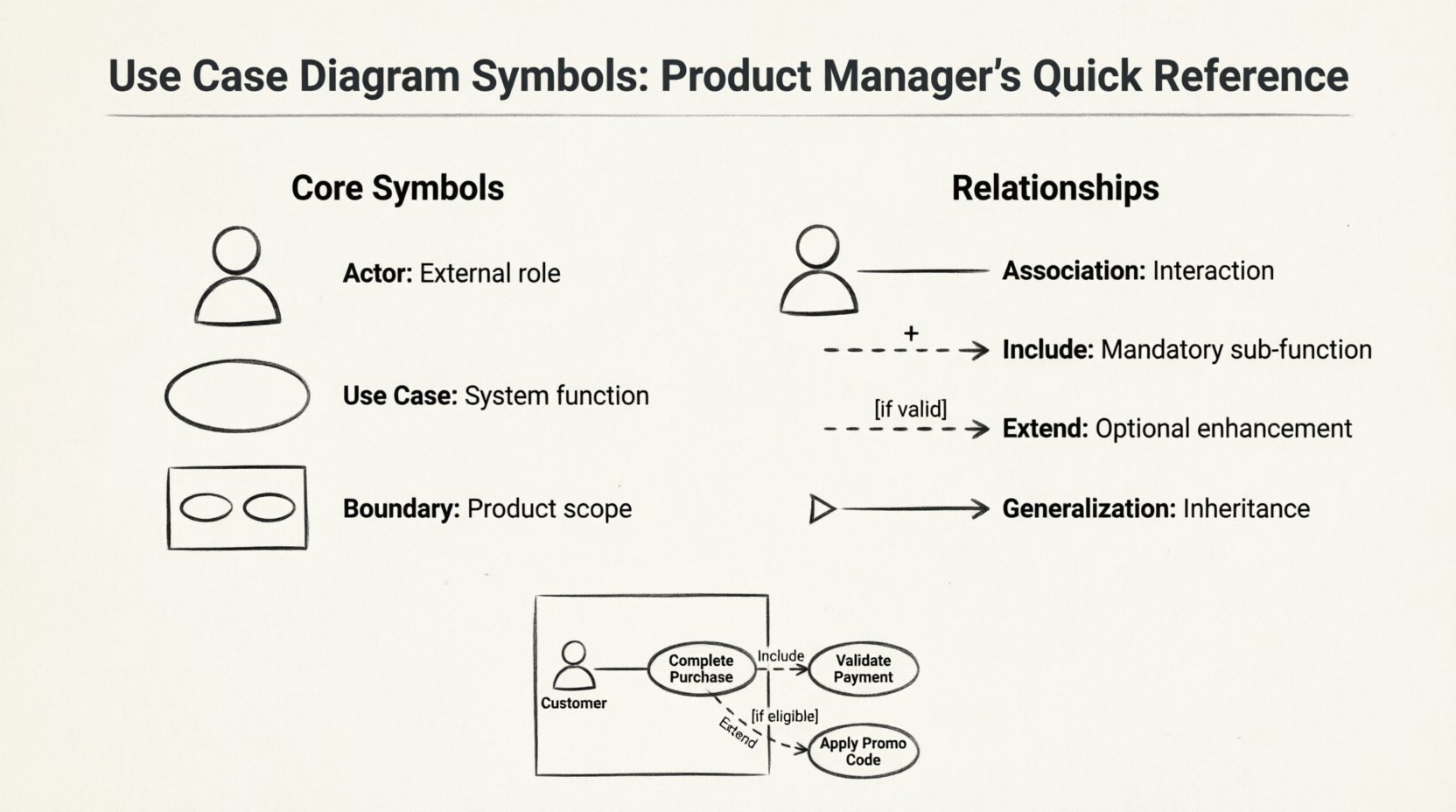
Every diagram is constructed from a specific set of symbols. Each carries distinct meaning regarding system boundaries and actor roles. Below is a detailed look at the primary elements you will encounter.
An Actor represents a role played by an external entity that interacts with the system. It is typically depicted as a stick figure. In product management, defining actors correctly is the first step in scoping.
Product Manager Insight: Avoid labeling actors with specific job titles that might change. Use functional roles instead (e.g., “Registered User” rather than “John from Marketing”). This ensures the diagram remains valid even as team structures evolve.
A Use Case is an oval shape representing a specific function or goal the system performs. It is a complete unit of functionality from the user’s perspective.
Product Manager Insight: Use cases are the foundation of your feature backlog. Each oval often translates directly into a user story or an epic, depending on the complexity.
The system boundary is a rectangle that encloses the use cases. It clearly defines the scope of the product.
Product Manager Insight: This is your primary tool for managing scope creep. If a request falls outside the boundary, it is not part of the current system version. This visual distinction helps in saying “no” or “not yet” to feature requests during sprint planning.
Relationships define how actors and use cases interact. Understanding these connections is vital for defining logic flows and dependencies.
A solid line connecting an Actor to a Use Case. It indicates that the actor participates in that use case.
Product Manager Insight: This is the most basic requirement. If there is no line, the actor cannot perform that action. Ensure every primary user journey has a clear association.
A dashed arrow with an open arrowhead pointing to the included use case. It indicates that the base use case must execute the included use case to complete its function.
Product Manager Insight: Use this to identify shared functionality across multiple features. If “Log In” is included in five different use cases, ensure the authentication logic is robust and consistent across the board.
A dashed arrow with an open arrowhead pointing to the base use case. It indicates that the extending use case adds behavior to the base use case under specific conditions.
Product Manager Insight: This is crucial for defining MVP (Minimum Viable Product) scope versus future enhancements. Treat “Extend” relationships as potential future features or conditional logic that can be deprioritized without breaking the core flow.
A solid line with a large triangular arrowhead pointing to the parent. It represents an “is-a” relationship.
Product Manager Insight: This helps in understanding access control and permissions. If a general use case is restricted to “Registered Users,” the “Premium User” automatically inherits that capability unless explicitly overridden.
Beyond the core symbols, diagrams often include additional elements to clarify context.
A rectangle with a folded corner, connected by a dashed line. It provides comments, constraints, or explanations.
A folder icon used to group related use cases. It helps manage complexity in large systems.
To visualize how these symbols work together, consider a typical e-commerce checkout flow. This example demonstrates how a Product Manager might map requirements.
Scenario: Online Purchase
In this setup, the Product Manager can clearly see that the core flow relies on payment validation. The promo code is an optional enhancement. The boundary ensures that the email service is treated as part of the system, even if outsourced.
Creating a diagram is easy; creating a useful one is difficult. Follow these guidelines to ensure your diagrams drive value.
Even experienced teams fall into traps when modeling. Be aware of these common pitfalls.
Refer to this table for a quick lookup during your planning sessions.
| Symbol | Name | Meaning | Product Manager Focus |
|---|---|---|---|
| 👤 Stick Figure | Actor | External entity interacting with the system | Identify user roles and permissions |
| 🔵 Oval | Use Case | Specific function or goal | Define features and user stories |
| 📦 Rectangle | System Boundary | Scope of the product | Manage scope creep and boundaries |
| ↔️ Solid Line | Association | Interaction between Actor and Use Case | Map user journeys |
| ➕ Dashed Arrow | Include | Mandatory sub-function | Identify shared dependencies |
| 🛠️ Dashed Arrow | Extend | Optional sub-function | Identify future enhancements |
| 📉 Triangle Arrow | Generalization | Inheritance relationship | Handle permissions and variants |
| 📌 Folded Corner | Note | Comment or constraint | Clarify business rules |
How do you take these symbols and put them into practice? The integration happens during the discovery and planning phases.
By treating the diagram as a contract between business and engineering, you reduce ambiguity. When a developer asks, “Does this feature require authentication?” you can point to the Include relationship and provide a definitive answer.
Mastering the visual language of requirements is a skill that pays dividends over time. It shifts your focus from managing tasks to managing value. By accurately representing actors, boundaries, and relationships, you create a blueprint that withstands the pressure of changing requirements.
Remember that the goal is clarity, not complexity. If a diagram confuses a stakeholder, it has failed its purpose. Simplify. Iterate. Validate. The symbols are tools to facilitate conversation, not the conversation itself.
As you move forward, keep this reference handy. Whether you are defining a new feature set or refactoring an existing system, a clear Use Case Diagram will serve as your anchor. It ensures that every line of code written aligns with the user’s intent and the product’s strategic goals. Start mapping, start clarifying, and start building with precision.