 Visual Paradigm Desktop |
  Visual Paradigm Online


System modeling is a critical phase in software development and requirements engineering. It provides a structured way to visualize how users interact with a system and what functions the system performs. Among the various modeling techniques available, the Use Case Diagram stands out for its simplicity and effectiveness in capturing functional requirements. This guide provides a detailed examination of the three core components of a Use Case Model: Actors, Boundaries, and Relationships. By understanding these elements, teams can create clearer specifications that align technical implementation with user needs.
Effective modeling requires precision. Ambiguity in diagrams often leads to misinterpretation during the development phase. This article explores the mechanics of Use Case modeling without relying on specific tools or proprietary platforms. The focus remains on the theoretical and practical application of the concepts.
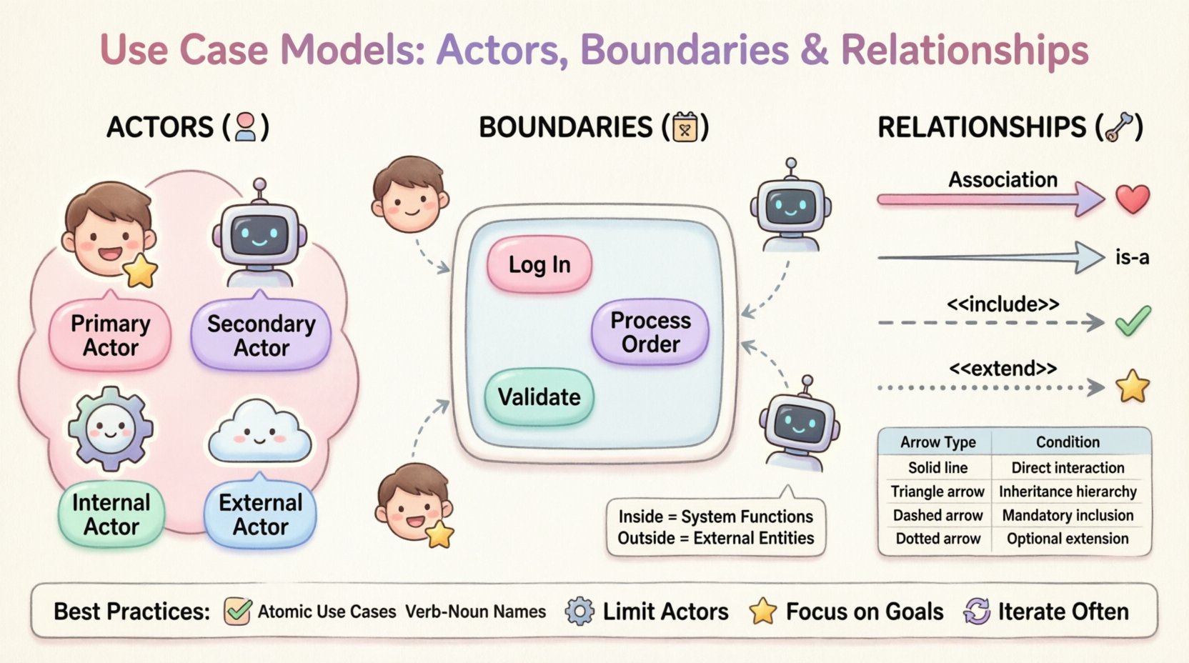
An actor represents a role played by an entity that interacts with the system. It is crucial to understand that an actor is not necessarily a person. While human users are the most common examples, actors can be other systems, hardware devices, or even time-based triggers. Identifying the correct actors is the first step in defining the scope of interaction.
Actors are generally categorized based on their relationship to the system and their level of interaction. Distinguishing between these types helps in organizing the diagram logically.
When defining actors, it is best to focus on the role rather than the specific individual. Instead of labeling an actor as “John Doe,” label it as “Administrator.” Roles remain consistent even if the personnel changes, ensuring the model remains valid over time.
The system boundary is a rectangular box that encloses all the use cases belonging to the system under consideration. It clearly distinguishes what the system does from what lies outside its control. This visual cue is essential for scope management.
| Element | Location Relative to Boundary | Responsibility |
|---|---|---|
| Use Cases | Inside | Functions performed by the system |
| Actors | Outside | Entities interacting with the system |
| Relationships | Crossing | Communication lines between actors and use cases |
Defining the boundary is often more challenging than identifying actors. If a boundary is too wide, the model becomes cluttered and loses focus. If it is too narrow, necessary dependencies may be excluded. A good rule of thumb is to include only functions that are directly controlled by the system developers or stakeholders.
The boundary also defines the context of the system. Anything outside the box is considered an external dependency or an environmental factor. This distinction is vital when analyzing failure points. If a secondary actor fails, does the system fail, or can it handle the error? The boundary helps answer these questions by isolating the system’s internal logic from external variability.
Relationships connect actors to use cases and use cases to other use cases. These lines define the flow of information and control. There are four standard types of relationships used in Use Case modeling. Understanding the distinction between them prevents logical errors in the design.
An association is a solid line connecting an actor to a use case. It indicates that the actor interacts with the use case. This is the most basic relationship.
Generalization represents an “is-a” relationship. It allows for the reuse of behavior. In Use Case modeling, it is used when one actor or use case is a specialized version of another.
The include relationship is used to modularize behavior. It indicates that one use case incorporates the behavior of another use case as a mandatory step. The included use case is essential for the base use case to complete.
The extend relationship represents optional behavior. It indicates that a base use case can be extended by another use case under specific conditions. Unlike include, the extended behavior is not required for the base use case to function.
| Relationship | Arrow Direction | Condition | Use Case |
|---|---|---|---|
| Association | None / Bidirectional | Interaction | Actor initiates action |
| Generalization | Base to Derived | Inheritance | Specialization of behavior |
| Include | Base to Included | Mandatory | Mandatory sub-function |
| Extend | Extension to Base | Optional | Conditional sub-function |
Creating a Use Case model is not just about drawing boxes and lines; it is about communication. The diagram must be understood by developers, stakeholders, and testers. Adhering to best practices ensures the model remains a useful reference throughout the project lifecycle.
Even experienced modelers can fall into traps that reduce the value of the diagram. Being aware of common mistakes helps maintain quality.
The value of a Use Case model lies in its ability to bridge the gap between business needs and technical implementation. It serves as a contract between stakeholders and the development team. By meticulously defining actors, boundaries, and relationships, teams reduce the risk of misunderstanding requirements.
Remember that modeling is a tool for thinking, not just for documentation. The process of drawing the diagram often reveals gaps in logic or missing requirements before any code is written. This proactive approach saves time and resources in the long run.
As you apply these concepts, focus on clarity and consistency. A well-structured Use Case model is a testament to a well-understood system. It facilitates communication, guides testing efforts, and ensures that the final product delivers the intended value to its users.
Continuously refine your diagrams based on feedback. Software development is iterative, and so should be your modeling process. By maintaining high standards in your diagrams, you contribute to a robust and reliable software engineering workflow.