 Visual Paradigm Desktop |
  Visual Paradigm Online


Creating a clear system design is fundamental to successful software development. Among the various modeling techniques available, the Use Case Diagram stands out as a primary tool for capturing functional requirements. However, experience shows that teams frequently encounter significant hurdles when constructing these diagrams. Misinterpretations of actors, ambiguous boundaries, and inconsistent relationship definitions often lead to wasted time and misaligned expectations.
This guide addresses the specific friction points that cause confusion. By understanding the root causes of these issues, teams can implement structured approaches to clarify scope, improve communication, and ensure the diagram accurately reflects system behavior.
Confusion rarely stems from a lack of effort. It typically arises from conceptual overlaps and vague definitions. When stakeholders, business analysts, and developers approach the diagram with different mental models, the resulting artifact becomes a source of contention rather than clarity.
Addressing these issues requires a shift from drawing boxes to defining intent. The goal is to create a visual contract that everyone understands, regardless of their technical background.
To resolve confusion, we must dissect the fundamental building blocks. Precision here prevents errors downstream in the development lifecycle.
An actor represents an entity that interacts with the system. It is crucial to remember that an actor is not necessarily a human. It can be another system, a device, or a scheduled process.
Common Error: Creating an actor for every single job title within a department. If two users perform the exact same set of actions, they should be represented by a single actor labeled with a generic role, such as “Administrator” or “Manager,” rather than “John Smith” or “Jane Doe.” This keeps the diagram scalable.
A use case represents a specific goal that an actor wants to achieve. It is a verb-noun phrase, such as “Place Order” or “Generate Report.” It describes the what, not the how.
The lines connecting actors to use cases define the interaction. There are four main types of relationships that need clear definition to avoid ambiguity.
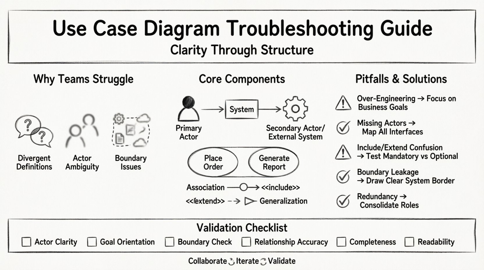
The following table outlines frequent errors observed during diagram creation and provides actionable solutions to correct them.
| Pitfall | Description | Resolution Strategy |
|---|---|---|
| Over-Engineering | Attempting to model every single screen or UI interaction. | Step back and focus on business goals. Ask: “What value does this provide?” |
| Missing Actors | Focusing only on human users and ignoring external systems. | Identify all interfaces. Does the system send emails? Does it receive data from a sensor? |
| Confusing Include/Extend | Using “Extend” for mandatory steps or “Include” for optional ones. | Test the logic. If the main process fails without the step, it is “Include.” If it is optional, it is “Extend.” |
| Boundary Leakage | Placing internal processes (e.g., “Database Query”) as use cases. | Draw the system boundary clearly. Anything strictly inside the system is not a use case. |
| Redundancy | Multiple actors with identical capabilities. | Consolidate actors into roles. Use generalization if the roles differ significantly. |
One of the most persistent sources of friction is the level of detail. Some teams create diagrams so high-level that they are useless for developers. Others create diagrams so detailed that they become obsolete after the first sprint.
To achieve the right balance, consider the purpose of the diagram. If the goal is to gather requirements from business stakeholders, keep the language simple and goal-oriented. If the goal is to guide developers, ensure that the boundaries are clear regarding inputs and outputs.
A diagram is only as good as the consensus behind it. If the development team draws it without stakeholder input, it will fail. If stakeholders draw it without technical input, it will be unbuildable.
Organize workshops where stakeholders walk through scenarios verbally. As they describe a process, map it to the diagram in real-time. This reveals gaps in logic immediately. For example, a stakeholder might realize they forgot to account for a cancellation scenario during the discussion.
Assign specific review tasks to different groups.
Establish a style guide for the diagrams. Consistent shapes, line styles, and labeling conventions reduce cognitive load. If every team member uses the same visual language, reading the diagram becomes faster and less prone to misinterpretation.
Before finalizing the diagram, run it through this validation checklist. This ensures the artifact is robust and ready for handoff.
Requirements rarely stay static. As the project progresses, new features are added, and old ones are deprecated. The diagram must reflect these changes to remain relevant.
When a change is proposed, evaluate its impact on the diagram. Does it require a new actor? Does it modify an existing relationship? Documenting the version history of the diagram helps track the evolution of the system requirements over time.
Confusion surrounding Use Case Diagrams is manageable when approached systematically. By focusing on clear definitions, maintaining appropriate granularity, and fostering open collaboration, teams can transform these diagrams from sources of frustration into powerful tools for understanding.
The objective is not perfection, but clarity. A diagram that facilitates discussion and aligns expectations is more valuable than one that looks perfect but is ignored. Regular reviews, adherence to standards, and a willingness to refine the model based on feedback will ensure the team stays on track.
Start by auditing your current diagrams against the common pitfalls listed above. Identify the areas causing the most friction and apply the resolution strategies. With consistent effort, the process of modeling system behavior becomes a streamlined part of the development lifecycle, supporting rather than hindering progress.