 Visual Paradigm Desktop |
  Visual Paradigm Online


In the fast-paced environment of software development, assumptions are the enemy of delivery. When teams guess what users actually require, features often miss the mark, leading to wasted sprints and frustrated stakeholders. This is where the Use Case Diagram becomes an essential tool. It provides a visual contract between business goals and technical implementation.
For Agile teams, clarity is currency. A well-constructed diagram does more than just map interactions; it aligns the entire squad on the scope of work before a single line of code is written. This guide explores how to construct these diagrams effectively without relying on complex proprietary tools or rigid methodologies.
Agile methodologies prioritize responsiveness to change, but this does not mean ignoring requirements. The danger lies in the “interpretation gap.” When a Product Owner describes a feature verbally, developers interpret it differently than designers, and QA testers interpret it differently again.
A Use Case Diagram acts as a shared language. It forces the team to define who is doing what, and why, before the work begins. This reduces the cognitive load on developers, allowing them to focus on logic rather than deciphering intent.
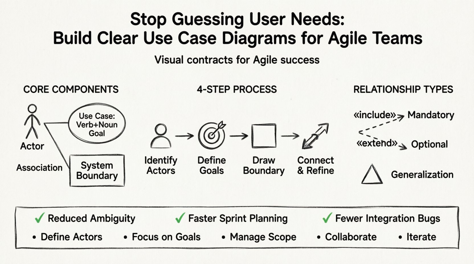
A Use Case Diagram is a behavioral diagram that depicts the interactions between a system and its external actors. It focuses on what the system does, not how it does it. This distinction is vital for maintaining the abstraction needed in high-level planning.
To build a clear diagram, you must understand the standard notation elements:
When these elements are arranged correctly, the diagram becomes a map of the system’s capabilities. It answers the question: “If I am this person, what can I achieve with this software?”
Some teams view documentation as an anti-pattern in Agile. They argue that working software is more valuable than comprehensive documentation. However, lightweight documentation like Use Case Diagrams serves a different purpose. It is not about creating a massive spec document; it is about creating a shared mental model.
When a team sits down for Sprint Planning, they often struggle to break down large epics into manageable stories. A Use Case Diagram helps visualize the flow.
Creating a diagram from scratch can feel overwhelming. To maintain clarity and authority, follow a structured process. This ensures consistency across different diagrams and different team members.
Start by listing everyone who interacts with the system. Do not overcomplicate this. Ask: “Who touches this software?”
Tip: If an actor does not have a goal to achieve, they might not need to be on the diagram. Keep it focused on value.
For each actor, list the goals they want to achieve. Use verb-noun phrases for clarity.
Ensure every use case provides value. If a step does not help the user achieve their goal, it might be a supporting process better suited for a Sequence Diagram later.
Draw a box around the use cases. Everything inside is part of your current scope. Everything outside is the environment. This helps prevent scope creep during development.
Draw lines between actors and the use cases they initiate. A solid line indicates an association. This shows the direct relationship.
Complex systems require more than simple lines. To capture the nuance of interactions, use the following relationships.
Use this when a use case must call another use case to complete its task. It is a mandatory dependency.
Use this for optional behavior. The extended use case runs only under specific conditions.
Use this when actors or use cases share common traits.
| Relationship Type | Notation | Meaning | Use Case |
|---|---|---|---|
| Association | Solid Line | Basic communication | Actor initiates a use case |
| Include | Dashed Arrow (< |
Mandatory inclusion | Shared functionality required by multiple use cases |
| Extend | Dashed Arrow (< |
Optional behavior | Special cases or error handling |
| Generalization | Solid Triangle Arrow | Parent-Child relationship | Specialized actors or functions inheriting traits |
Even experienced teams make errors when modeling. Avoid these pitfalls to maintain diagram clarity.
Do not draw specific buttons or screen layouts. A Use Case Diagram is about the system’s behavior, not the UI. Avoid writing “Click Submit Button” as a use case. Instead, use “Submit Form”.
If you have more than 10 actors, the diagram becomes unreadable. Group them logically. For example, if you have “Admin”, “Manager”, and “Supervisor”, consider if they can be grouped under “Staff” if their use cases are identical.
Modern software relies heavily on APIs and third-party services. Treat these as actors. If your system sends data to a CRM, the CRM is an actor. Failing to document this leads to integration failures later.
Names like “Process” or “Handle” are too vague. Always use a Verb + Noun structure. “Process Data” is better than “Process”.
Once the diagram is created, it must live in the workflow. It should not be a static document stored in a folder. It needs to be part of the daily rhythm.
Review the diagram with the Product Owner. Verify that every use case has corresponding user stories. If a use case has no stories, it might be a phantom requirement. If a story has no use case, it might be out of scope.
Keep the diagram accessible on the team’s whiteboard or digital workspace. When a developer encounters an ambiguity during coding, refer to the diagram. Does the current path align with the defined interaction?
If the team discovered new requirements mid-sprint, update the diagram. This visual record helps in understanding how the scope evolved and why certain decisions were made.
As software grows, a single diagram becomes impossible to read. This is known as “diagram sprawl.” To manage this, use packages or sub-systems.
Link these packages together using the main actors. This keeps the high-level view clean while allowing detailed views for specific domains.
Building these diagrams is rarely a solitary task. The best results come from collaboration. Here is how to approach it with the team.
This collaborative approach ensures that the diagram represents a consensus, not just one person’s interpretation.
How do you know if the diagram is actually helping? Look for these indicators.
As tools evolve, the core principles remain the same. Whether you use a simple text-based tool, a whiteboard, or a digital modeling environment, the goal is communication. The industry is moving towards model-driven development, where code is generated from models. While this is not standard for every team, the discipline of defining use cases early prepares you for that future.
Even if you never generate code from a diagram, the act of modeling forces critical thinking. It exposes logical holes before they become expensive bugs. In an Agile context, this is the difference between iterating on the right thing and iterating on the wrong thing.
Building software is not just about writing code; it is about solving problems for people. A Use Case Diagram puts those people at the center of the design process. It reminds the team that every feature exists to serve an actor’s goal.
By following the steps outlined in this guide, your team can move away from guessing and start building with clarity. Stop assuming you know what the user needs. Map it out, validate it, and execute with confidence.
Remember, the diagram is a living artifact. It should evolve as your product evolves. Keep it updated, keep it visible, and keep it useful. That is the mark of a mature engineering practice.
Implementing this approach will strengthen your Agile process and ensure that the final product truly meets user needs without the guesswork.