 Visual Paradigm Desktop |
  Visual Paradigm Online


In the complex landscape of Systems Engineering, making the right choice at the right time is critical. Systems are rarely built in a single pass; they evolve through a series of decisions. Each decision narrows the design space, locking in constraints and opening specific pathways. SysML, the Systems Modeling Language, offers structured ways to capture these moments of choice. This guide explores decision point modeling within SysML, focusing specifically on how to evaluate architecture options effectively. We will look at the mechanics of decision nodes, the integration of evaluation metrics, and the traceability required to support robust engineering choices. ⚙️
A decision point represents a moment in the system lifecycle or design process where a choice must be made. It is a branching node where the flow of logic diverges based on conditions, constraints, or stakeholder preferences. In a physical sense, this might be the selection of a propulsion system for a satellite. In a logical sense, it could be the activation of a safety protocol during operation.
Modeling these points explicitly prevents ambiguity. Without a model, decisions are often captured in static documents that lack traceability. When requirements change, the link between the decision and the rationale becomes severed. SysML brings these decisions into a dynamic, queryable state. By using standard modeling constructs, engineers can simulate outcomes before committing resources. 📊
SysML provides specific diagram types to represent decision logic. While Activity Diagrams are the most common, State Machine Diagrams offer alternatives depending on the nature of the decision. Understanding the distinction ensures the model remains accurate to the real-world behavior of the system.
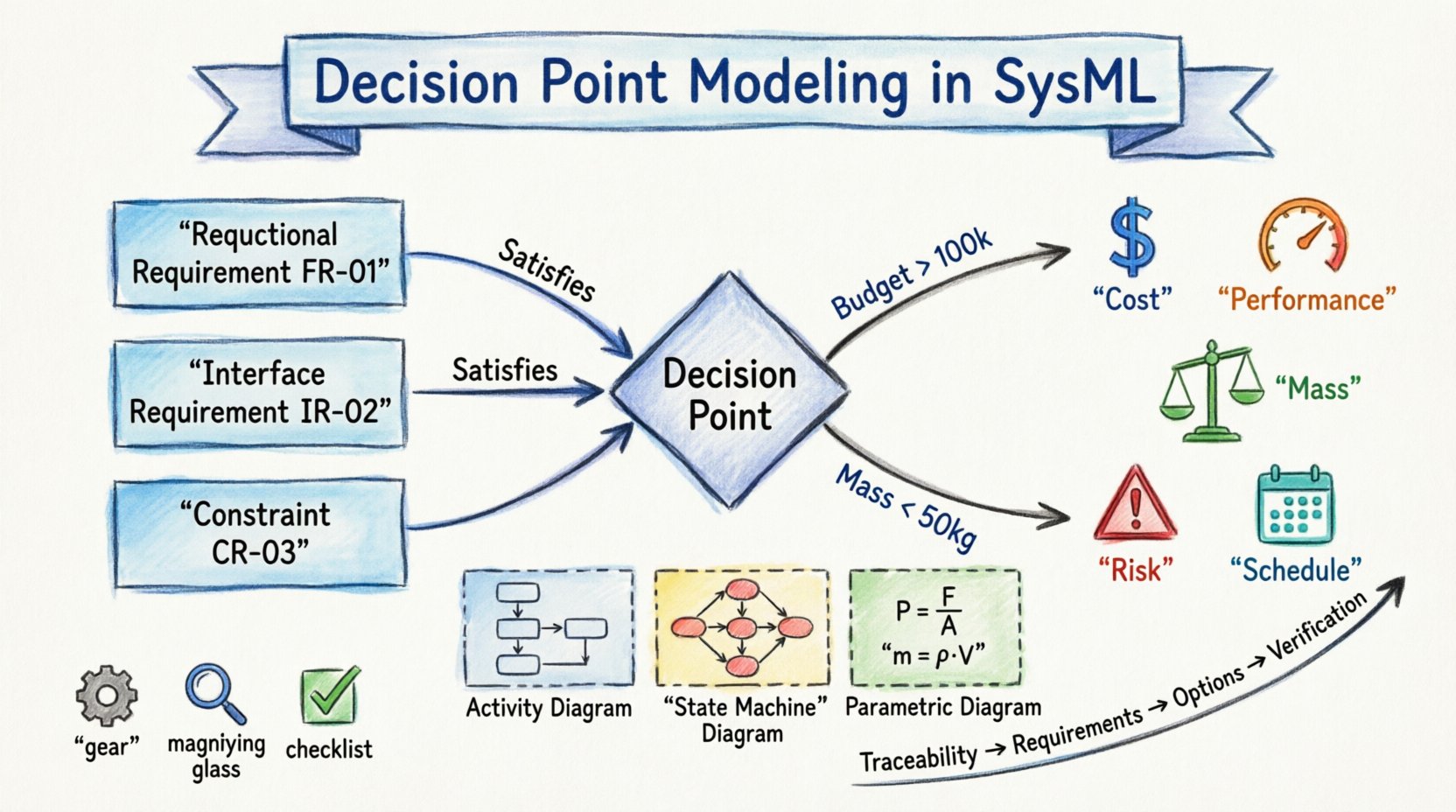
Activity Diagrams are ideal for modeling process flows where a decision is made based on data or state. The primary construct here is the Decision Node. This diamond-shaped symbol indicates a point where control flow splits into multiple outgoing flows. Each flow is guarded by a boolean expression.
When modeling architecture options, the Decision Node acts as a gateway. One path might lead to Option A, while another leads to Option B. The guard condition on the path determines which option is selected. For example, a guard condition might check if the budget is sufficient. If true, the path to the high-performance component is taken. If false, the path to the standard component is followed.
For decisions that relate to the state of the system itself, State Machine Diagrams are useful. The Choice Point serves a similar function to the Activity Decision Node but within the context of state transitions. This is particularly relevant for operational decisions that occur during system runtime.
When evaluating architecture options, State Machines help visualize how different configurations impact the system’s behavior over time. For instance, a decision to switch to a backup power source changes the state of the power management subsystem. Modeling this explicitly allows for verification of the transition logic.
Modeling a decision is only half the battle. The model must also support the evaluation of the options presented at that decision point. This requires linking the structural choices to quantitative and qualitative metrics. SysML supports this through Parametric Diagrams and Requirements relationships.
To evaluate an option, you must define what success looks like. Common metrics in systems engineering include:
In the model, these metrics can be represented as parameters or properties within the system blocks. When a decision node routes to a specific option, the associated parameters change. This allows for a comparative analysis within the model environment.
Parametric Diagrams allow you to define constraints and equations that govern the system. By connecting these constraints to the architecture options, you can calculate the impact of a decision. For example, if Option A requires a larger battery, the mass constraint will increase. If Option B uses a more efficient processor, the power constraint will decrease.
This approach moves decision-making from intuition to calculation. You can run simulations to see which option satisfies the most constraints. The model becomes a tool for analysis rather than just documentation. 🔍
Clarity is essential when multiple stakeholders are reviewing the model. The structure of the decision logic must be intuitive. Poorly structured models lead to misinterpretation and errors in downstream design.
Complex systems often have cascading decisions. One decision might enable or disable another. For example, selecting a specific sensor might require a specific data bus architecture. Modeling this hierarchy requires careful use of merge nodes to bring flows back together after divergence.
When multiple decisions exist, it is vital to visualize the decision space. A table can help summarize the combinations of options. This prevents combinatorial explosion where the model becomes too large to manage.
A decision is not valid in a vacuum. It must satisfy requirements. SysML provides the Requirement block and relationships to link decisions to these specifications. This ensures that every branch in the model has a justification.
Each architecture option should be linked to the specific requirements it addresses. This is done using the Satisfies relationship. If an option fails to meet a requirement, the model reflects this gap.
Furthermore, decision nodes can be linked to Constraints. These constraints define the boundaries within which the decision must operate. For example, a constraint might state that the selected option must not exceed a certain temperature threshold.
Verification ensures that the chosen architecture meets the intended goals. This is achieved by tracing requirements from the top level down to the specific decision nodes. If a requirement is verified, the decision that enabled it is validated. This creates a closed loop of evidence.
| Traceability Element | Purpose | Link Type |
|---|---|---|
| Requirement | Defines the need | Derived |
| Decision Node | Selects the path | Satisfies |
| Architecture Option | Implements the path | Refines |
| Verification Test | Validates the option | Verified |
Decision modeling does not exist in isolation. It is part of a broader Model-Based Systems Engineering (MBSE) process. The timing of decision modeling is critical. It should occur during the preliminary design phase, where options are still flexible.
During the concept phase, high-level decision nodes are used to compare major architectures. These are often abstract and do not contain detailed parameters. The goal is to eliminate clearly inferior options early. This reduces risk before detailed design begins.
As the design matures, decision nodes become more detailed. Guard conditions become specific engineering parameters. The model transitions from a strategic tool to a tactical one. This evolution must be managed to avoid model drift.
Even experienced modelers encounter challenges when implementing decision points. Recognizing these pitfalls helps maintain model integrity.
Beyond basic decision nodes, SysML allows for more sophisticated analysis. By combining decision modeling with simulation, teams can explore the future behavior of the system under different choices.
Scenario analysis involves running the model with different input values to see how the decision logic responds. This is useful for stress-testing the architecture. For example, what happens if the budget is cut by 20%? The model should automatically route to the lower-cost option if the guard conditions are set correctly.
Trade studies are formal evaluations of multiple options against weighted criteria. SysML supports this by allowing the definition of weighted parameters. These weights can be applied to the evaluation metrics, allowing the model to calculate a score for each option. The option with the highest score becomes the recommended path.
Models are tools for communication as much as they are for engineering. Decision point models provide a visual language for stakeholders to understand trade-offs. This is crucial when non-technical stakeholders must approve architectural choices.
A well-structured decision model makes trade-offs visible. Instead of reading pages of text, stakeholders can see the branching paths and the consequences of each. This transparency builds trust and facilitates faster approvals.
Every decision node should have an associated note or comment explaining the rationale. This text is not part of the executable logic but is vital for historical context. It explains why a specific guard condition was chosen. This documentation survives the project and aids future maintenance.
Maintaining the quality of a model with multiple decision points requires discipline. Consistency checks should be part of the regular engineering workflow.
Since decision points evolve, version control is essential. Changes to guard conditions or options should be tracked. This allows the team to revert to a previous state if a new decision proves untenable. It also provides an audit trail for regulatory compliance.
Decision point modeling in SysML transforms subjective choices into objective analysis. By embedding evaluation criteria directly into the model structure, engineers gain visibility into the implications of their designs. This approach reduces risk, improves traceability, and supports better communication among teams.
To implement this effectively, teams should start with high-level decisions and gradually refine the granularity. Focus on linking options to measurable metrics and ensuring requirements are traced through the decision logic. Avoid the temptation to model every minor choice; reserve the effort for decisions that define the architecture.
As systems become more complex, the need for structured decision-making grows. SysML provides the foundation for this rigor. By adhering to the practices outlined here, organizations can build systems that are robust, verifiable, and aligned with strategic goals. The model becomes a living record of the engineering journey, capturing not just what was built, but why it was built that way. 🧭