 Visual Paradigm Desktop |
  Visual Paradigm Online


In the landscape of complex system engineering, managing requirements is often the most critical challenge. Systems grow in complexity, interfaces multiply, and stakeholder needs evolve. Without a structured approach, information silos form, and the connection between a high-level stakeholder need and a low-level component specification becomes severed. This is where Model-Based Systems Engineering (MBSE) and the Systems Modeling Language (SysML) provide a robust foundation. Specifically, Requirement Flow Analysis serves as the backbone for maintaining integrity across the system lifecycle.
This guide explores how to establish and maintain end-to-end traceability using SysML constructs. We will examine the mechanics of requirement relationships, the integration of verification activities, and the strategies for managing change without losing context. The goal is to create a living model that reflects the system reality, ensuring every requirement is justified, designed, and verified.
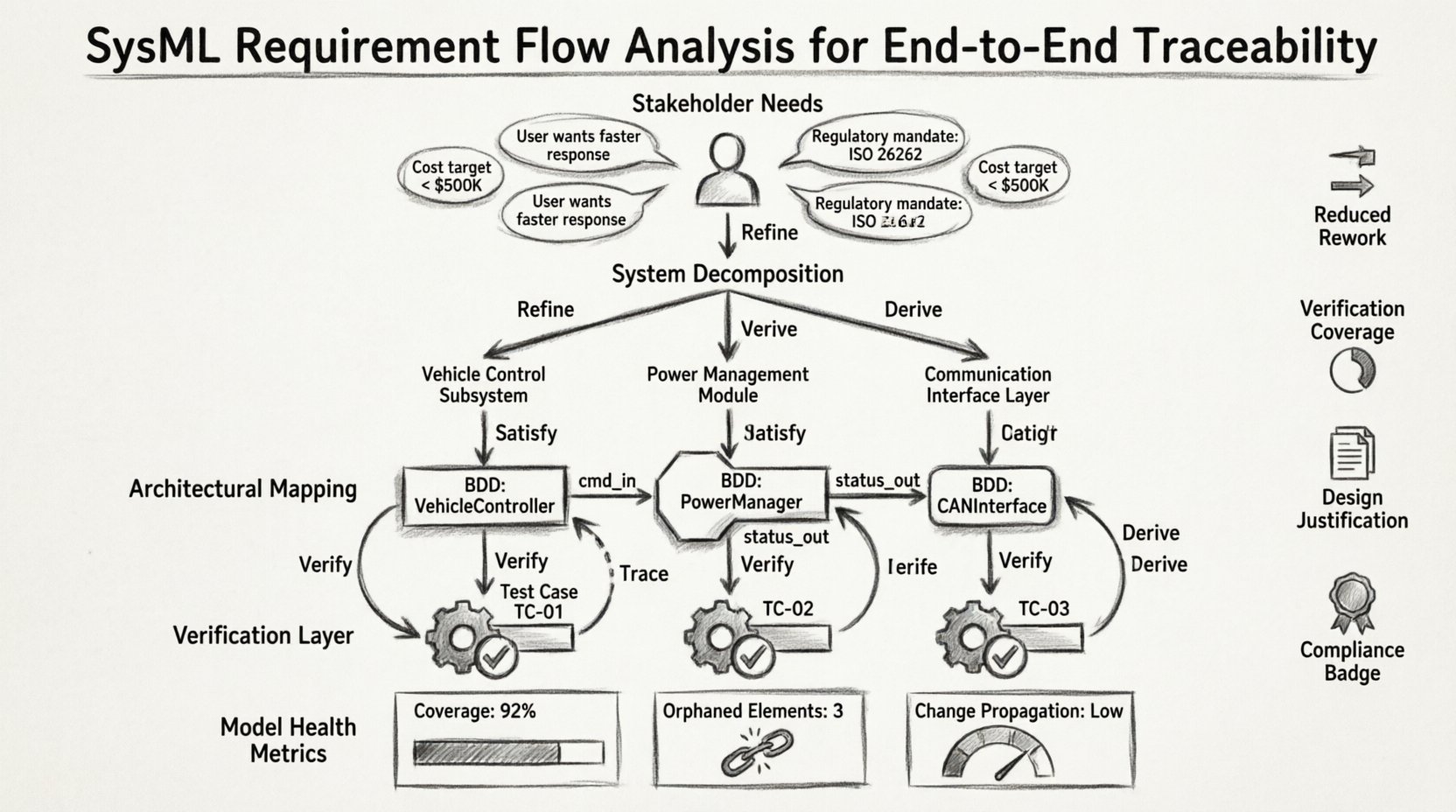
Requirement Flow Analysis is not merely about listing items in a database. It is the process of mapping the logical progression of needs from the user context through to the physical realization. In a traditional document-driven approach, traceability is often a linear spreadsheet exercise. In a modeling environment, it becomes a network of relationships.
When you perform flow analysis, you are essentially auditing the information path. You ask: Does this requirement exist in the model? Is it linked to a block? Is it linked to a test? If any link is missing, the flow is broken. A broken flow leads to ambiguity, rework, and potential safety issues.
Traceability is often viewed as a compliance checkbox. However, its value lies in risk reduction and decision support. When requirements are fully traced, the impact of any change is visible immediately. If a stakeholder requests a modification to a performance metric, you can instantly see which subsystems, interfaces, and test cases are affected.
The benefits of rigorous traceability include:
SysML provides specific diagram types and relationship types designed to handle requirements. Understanding these elements is essential for accurate modeling.
The Requirement block is the atomic unit of traceability. It should be uniquely identified, typically using a hierarchical ID (e.g., SYS-REQ-001). Each requirement should contain specific properties:
This diagram is dedicated solely to requirements and their relationships. It allows you to group requirements logically and define the flow between them. You should not clutter this diagram with blocks or use cases unless necessary for context.
The power of SysML lies in its relationships. These define the direction and nature of the trace:
Constructing a flow analysis model requires a disciplined approach. You cannot simply dump requirements into a diagram and expect traceability to work. The model must be built in layers.
Start with the System Context. Define the top-level requirements that represent the user’s mission. These are often qualitative or high-level quantitative statements. Link these to the external entities interacting with the system.
Break the top-level requirements down into functional requirements. Use the Refine relationship to create a tree structure. This ensures that the sum of the parts equals the whole.
This is where the model transitions from abstract needs to concrete structure. You will use Block Definition Diagrams (BDD) and Internal Block Diagrams (IBD) to represent the system architecture.
A common pitfall is treating requirements and design as separate streams. They must converge. The flow analysis ensures that the design is not just functional, but compliant.
| Traceability Direction | Relationship Type | Purpose | Example |
|---|---|---|---|
| Requirement to Requirement | Refine / Derive | Establish Hierarchy | System Req refined by Subsystem Req |
| Requirement to Block | Satisfy | Design Compliance | Power Supply Block satisfies Power Req |
| Requirement to Operation | Allocate | Functional Allocation | Operation ‘Start Engine’ satisfies Control Req |
| Requirement to Test | Verify | Validation | Test Case ‘Check Voltage’ verifies Power Req |
When mapping elements, use a consistent naming convention. A requirement ID should be visible in the trace. For example, if a block is named PowerSupply_01, the requirement it satisfies might be REQ_PWR_001. This consistency aids in automated reporting.
Traceability is incomplete without verification. A requirement that is designed but never tested is a liability. SysML allows you to link verification activities directly to requirements.
Verification activities can be represented as:
Using the Verify relationship is critical here. It creates a closed loop. When a test fails, the trace highlights the specific requirement that is not met. This allows for rapid root cause analysis. If the test fails due to a component error, the trace shows you exactly which requirement the component was supposed to satisfy.
Real-world systems rarely have linear relationships. Requirements often depend on each other. Some requirements might be conditional based on configuration options. Managing these dependencies requires careful modeling.
Not all systems operate in all modes. Use the Derive or Refine relationships to show conditional logic. You might have a requirement that is active only when a specific mode is selected. Document this condition in the requirement property or via a guard condition on the relationship.
Requirements often span multiple subsystems. A latency requirement might involve both software and hardware. Use Internal Block Diagrams to visualize the data flow between these blocks. Ensure that the interface definition matches the requirement constraints.
SysML is multi-view. A requirement might be described in a Requirement Diagram, allocated in a BDD, and tested in a Test Case diagram. Ensuring these views stay synchronized is a major challenge. Regular audits of the model are necessary to ensure that a change in one diagram does not break the trace in another.
Achieving high-quality traceability is difficult. Teams often fall into traps that reduce the value of the model over time.
Linking everything to everything else creates a “spaghetti model” that is hard to navigate. Only link what is necessary. If a requirement is satisfied by a general system behavior, do not link it to every specific block unless that block is critical.
If one level of the hierarchy is very detailed and the next level is vague, the trace becomes meaningless. Ensure that the level of detail is consistent across the decomposition tree.
Updating the model is often harder than updating a Word document. Teams tend to stop updating the model once it is created. Treat the model as the single source of truth. If a change happens, the model must be updated first.
Establish a strict naming standard. Use prefixes to denote type (e.g., REQ, BLK, INT). This makes searching and filtering easier when using model analysis tools.
Schedule periodic reviews of the traceability graph. Check for:
Use scripting or built-in analysis features to generate traceability reports. Manual checking is prone to human error. Automated reports provide an objective view of coverage and gaps.
Change is inevitable. A requirement might change due to new regulations, technology shifts, or user feedback. The strength of a SysML model is its ability to show the ripple effect of these changes.
When a requirement is modified:
This process transforms change management from a guessing game into a data-driven decision. You know exactly who to contact and what to test.
How do you know if your traceability is working? You need metrics. Quantitative measures help identify areas of risk.
Aim for 100% coverage on critical requirements. For lower priority items, a lower threshold may be acceptable, but it should be documented. Consistent tracking of these metrics over time reveals trends. If coverage drops, it indicates a breakdown in the engineering process.
SysML does not exist in a vacuum. It must integrate with other lifecycle phases, such as software development, manufacturing, and maintenance. The traceability model should serve as the bridge between these domains.
This integration ensures that the system does not end at the point of delivery. The traceability chain extends through the entire operational life of the product.
Implementing SysML requirement flow analysis is a significant investment of time and effort. It requires discipline, training, and a commitment to model integrity. However, the return on investment is a system that is easier to understand, easier to change, and easier to certify.
By focusing on the relationships rather than just the content, you build a robust framework for system engineering. The flow analysis ensures that the logic of the system is preserved, even as the details evolve. Start with the critical paths, ensure the top-level requirements are solid, and expand the traceability outward. Avoid shortcuts that compromise the quality of the links. A clean model is more valuable than a complete model with broken links.
Remember that the goal is not just to create a diagram. The goal is to create a reliable knowledge base that supports decision-making throughout the project lifecycle. With rigorous flow analysis, you ensure that every part of the system has a purpose, and every purpose is verified.