 Visual Paradigm Desktop |
  Visual Paradigm Online


In the world of object-oriented system design, visualizing the physical structure of a system is just as crucial as understanding its logical behavior. UML Component Diagrams serve this exact purpose. They are designed to model the physical aspects of object-oriented systems, providing a clear view of how components differ, interact, and form a complete software architecture.

This comprehensive guide will walk you through the definition, notations, relationships, and practical applications of Component Diagrams, helping you document system architecture effectively.
Before diving into complex diagrams, it is essential to understand the foundational terminology used in Component Diagrams. These definitions form the building blocks of your models.
subsystem.UML Component diagrams are essentially class diagrams with a specific focus on a system’s components. They are used to model the static implementation view of a system. By breaking down the actual system under development into high levels of functionality, these diagrams help architects and developers understand the structural organization of dependencies.
In a standard diagram, each component is responsible for a distinct aim within the system. Components interact only with essential elements on a need-to-know basis. A typical flow involves:
Note: A component can represent the overall system (a large box surrounding internal parts) or a single subsystem within a larger architecture.
Graphically, a component diagram is a collection of vertices and arcs. Understanding the specific notation is vital for creating readable models.
In UML 2, a component is drawn as a rectangle with optional compartments. It typically includes:
<<component>>, <<file>>, or <<database>>).Components are connected via various relationships that define how they interact physically and logically.
Component diagrams are versatile and can be applied to source code, executables, and databases.

You can model source code files (C++, Java, etc.) as components to visualize compilation dependencies. This is useful for forward and reverse engineering.
<<file>>.When modeling deployment, you identify the set of components that live on a specific node.

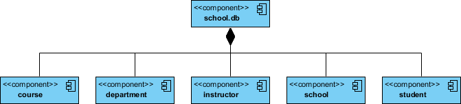
Component diagrams can visualize the mapping between logical classes and physical database tables.
<<tables>>.Creating complex component diagrams manually can be time-consuming. Visual Paradigm AI transforms this process by leveraging artificial intelligence to automate and enhance modeling.
UML Component Diagrams are indispensable for developers and architects aiming to document the physical structure of a system. Whether you are modeling source code dependencies, planning an executable release, or mapping a physical database, these diagrams provide the necessary clarity.
To get started, creating these diagrams doesn’t have to be expensive or difficult. Visual Paradigm Community Edition is an award-winning, free UML software that supports all UML diagram types. It offers an intuitive interface to help you learn and apply UML faster.
Ready to streamline your software architecture? Download Visual Paradigm today and turn every software project into a successful one.
https://guides.visual-paradigm.com/mastering-state-diagrams-in-uml-a-comprehensive-guide/
https://guides.visual-paradigm.com/understanding-sequence-diagrams-a-comprehensive-guide/
https://guides.visual-paradigm.com/creating-sequence-diagrams-in-uml-a-comprehensive-tutorial/
https://guides.visual-paradigm.com/category/visual-modeling/page/3/
https://blog.visual-paradigm.com/understanding-uml-component-diagrams-a-comprehensive-guide/
https://www.visual-paradigm.com/guide/uml-unified-modeling-language/what-is-component-diagram/
https://www.visual-paradigm.com/guide/uml-unified-modeling-language/uml-class-diagram-tutorial/
https://online.visual-paradigm.com/diagrams/tutorials/component-diagram-tutorial/
https://www.visual-paradigm.com/guide/uml-unified-modeling-language/uml-practical-guide/