 Visual Paradigm Desktop |
  Visual Paradigm Online


Data Flow Diagrams (DFDs) serve as the backbone of system architecture and process modeling. They visualize how information moves through a system, identifying inputs, outputs, and transformations. However, even experienced analysts encounter scenarios where the diagram no longer reflects the reality of the underlying process. When a DFD fails, it creates a disconnect between design and execution, leading to integration errors and maintenance nightmares. 🛑
This guide explores the five most common hidden issues that cause Data Flow Diagrams to lose accuracy and utility. By understanding these pitfalls, teams can maintain high fidelity in their system documentation and ensure that the model remains a reliable tool for development and analysis.
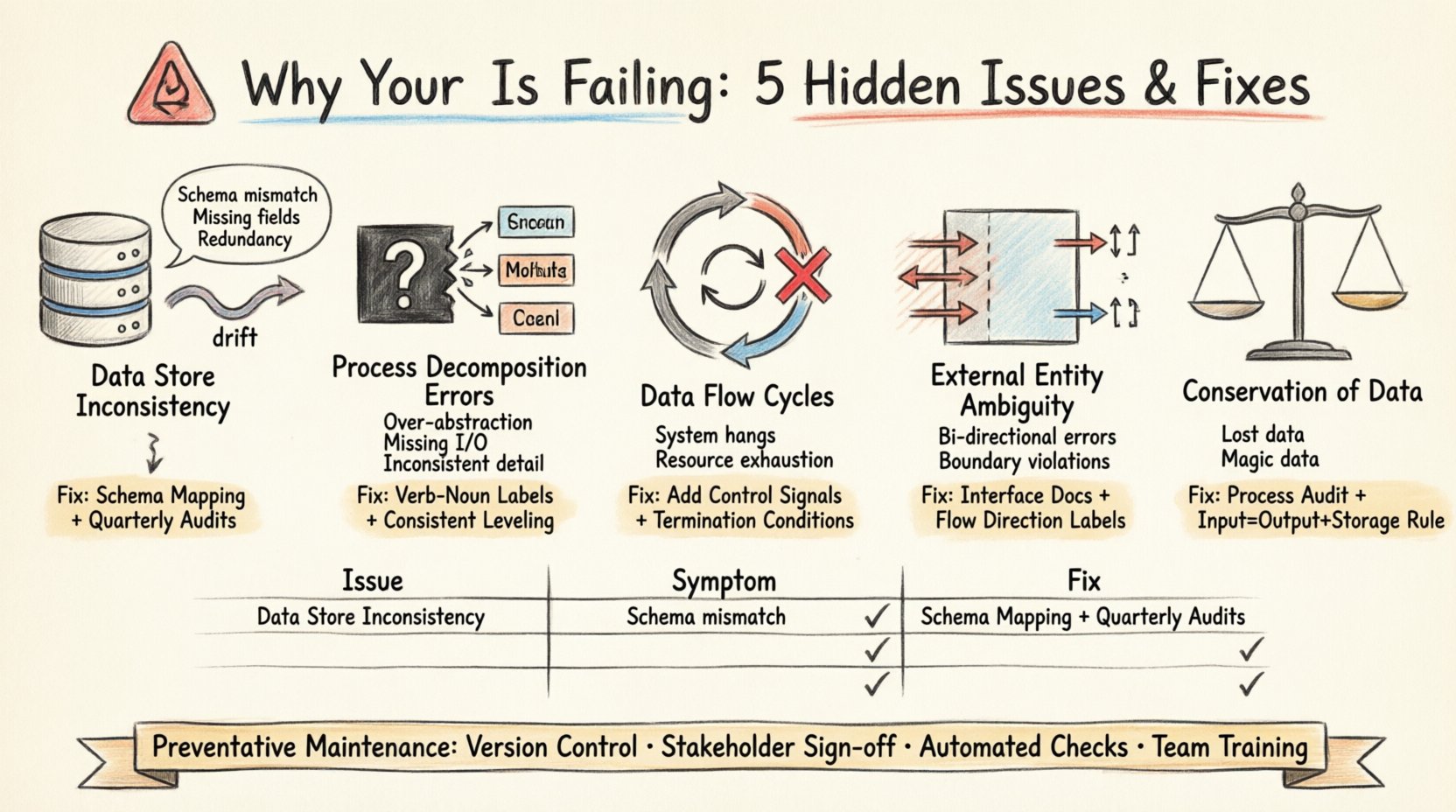
One of the most frequent failures in DFD maintenance is the divergence between the diagrammed data stores and the actual physical implementation. Over time, database schemas change, tables are split, or data retention policies shift. If the DFD does not update in parallel, it becomes a source of confusion rather than clarity.
To troubleshoot this, conduct a rigorous audit of the current system schema against the diagram. Verify that every data store in the DFD maps to an active physical or logical repository.
DFDs rely on hierarchical decomposition to manage complexity. A high-level process is broken down into sub-processes. A common failure occurs when these sub-processes are defined vaguely, creating a “black box” that obscures critical logic. This leads to ambiguity during implementation, as developers do not know exactly what transformation is expected.
Effective troubleshooting requires walking through each process with the logic layer. Ensure that every child process has defined inputs and outputs that sum up to the parent process’s data flow.
In a well-structured DFD, data should flow linearly from source to destination with transformations in between. However, hidden cycles can emerge where data flows back into a previous process without a terminating condition. In a physical system, this represents an infinite loop or a deadlock. In a diagram, it indicates a logical error in the process flow.
Tracing the data path is essential to identify these cycles. Look for arrows that return to an earlier stage in the hierarchy without an explicit control signal or termination condition.
External entities represent sources or destinations outside the system boundary. A common failure is confusing the direction of data flow or the nature of the interaction. Is the entity providing data, receiving data, or both? Ambiguity here leads to integration failures when connecting to third-party systems or user interfaces.
Clear definition of the system boundary is crucial. Every arrow crossing this boundary must be explicitly categorized as an input or output.
A fundamental principle of DFDs is the conservation of data. Every input into a process must result in an output, or be stored. If data enters a process and disappears without a trace, it violates this principle. Conversely, if data appears without an input source, it is “magic data,” which implies a flaw in the logic.
This issue often arises when processes are added or modified without updating the surrounding context. It leads to data loss or corruption in the actual system.
Once these issues are resolved, the focus must shift to prevention. A DFD is a living document that requires care. Without a maintenance strategy, the diagram will inevitably drift from reality again.
| Issue Category | Primary Symptom | Recommended Fix |
|---|---|---|
| Data Store Drift | Schema mismatch | Schema Mapping & Audit |
| Decomposition Errors | Black box logic | Verb-Noun Labeling |
| Data Flow Cycles | Infinite loops | Introduce Control Signals |
| Entity Ambiguity | Boundary confusion | Interface Documentation |
| Data Conservation | Missing inputs/outputs | Process Audit |
When a DFD fails, the consequences extend beyond documentation. Development teams rely on these diagrams to understand dependencies. If the model is flawed, the code written will be flawed.
Maintaining a valid Data Flow Diagram requires vigilance. By addressing the five hidden issues outlined here—Data Store Inconsistency, Process Decomposition Errors, Data Flow Cycles, External Entity Ambiguity, and Conservation of Data—teams can ensure their models remain accurate. A well-maintained DFD is not just a drawing; it is a contract between design and implementation.
Regular reviews, strict adherence to modeling standards, and a culture of documentation integrity will prevent the silent drift that plagues many projects. Treat the diagram with the same rigor as the code it represents.
Start your troubleshooting session today. Audit your current diagrams against these five criteria. The clarity you gain will save significant time during development and testing phases.