 Visual Paradigm Desktop |
  Visual Paradigm Online


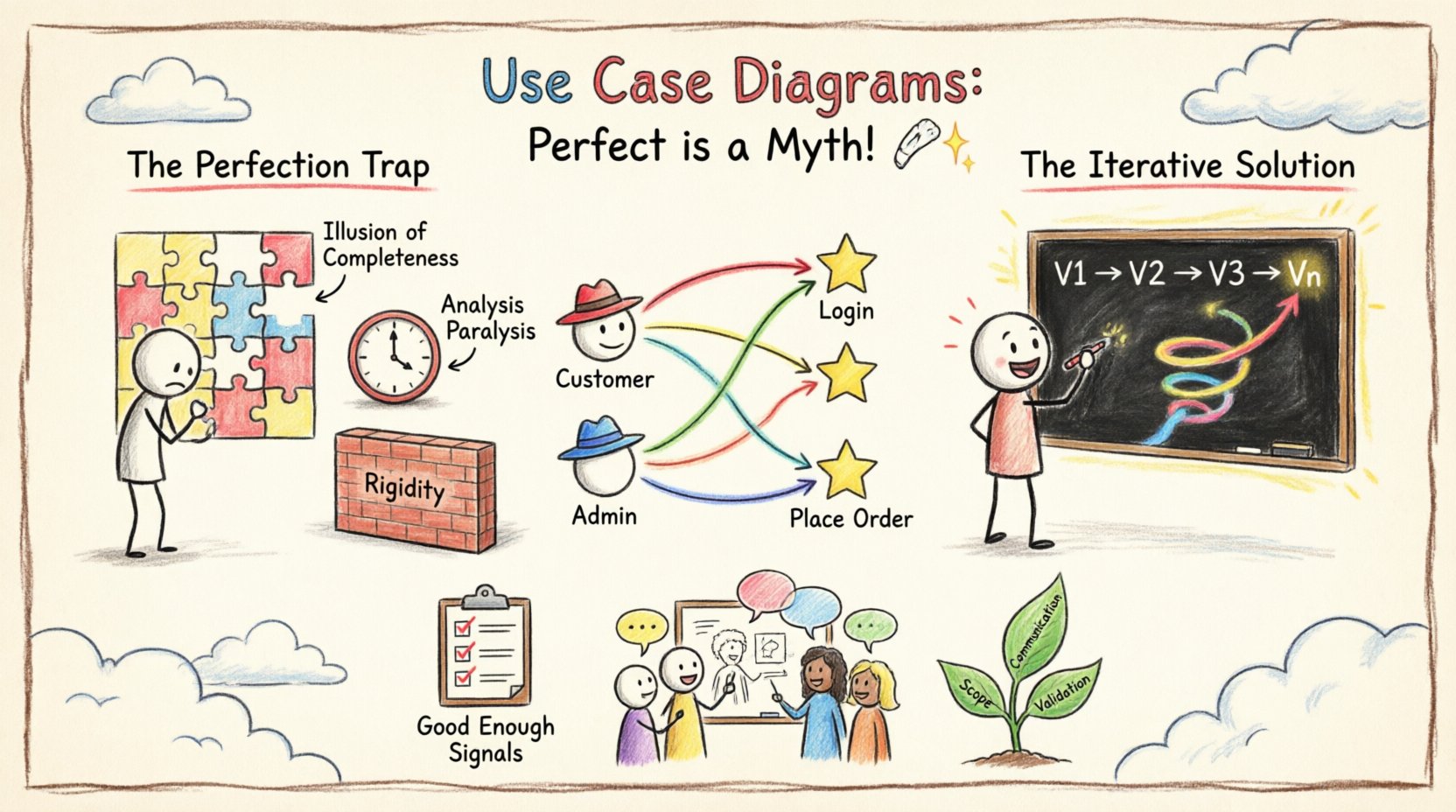
In the landscape of system design, few artifacts are as scrutinized as the Use Case Diagram. Stakeholders often arrive at modeling sessions with a clear expectation: they want a map that is complete, accurate, and definitive. They ask for the "final" diagram before the first line of code is written. This expectation creates a psychological trap known as the Perfection Paradox. When you strive for a flawless representation of a complex, evolving system, you often end up with a diagram that is obsolete the moment it is finished. 🛑
This guide addresses the reality of iterative modeling. We will explore why a static, perfect diagram is a myth, how to structure your diagrams for longevity, and the practical steps to refine them over time. By shifting your mindset from static completion to dynamic evolution, you can create diagrams that actually serve the development team and stakeholders effectively. 🔄
Before dismantling the myth of perfection, it is necessary to ground ourselves in what these diagrams are intended to do. A Use Case Diagram is a visual representation of interactions between a system and external entities. It focuses on what the system does, not how it does it. This distinction is critical for managing scope and expectations.
The diagram serves three primary functions:
When a diagram is treated as a permanent, unchangeable artifact, it ceases to function as a communication tool. It becomes a static document that ignores the fluidity of human requirements. Requirements change. Stakeholders forget details. New technologies emerge. The diagram must reflect these shifts.
The desire for a "perfect" diagram stems from a need for certainty. In software development, uncertainty is the only certainty. Striving for perfection in the initial modeling phase leads to several tangible issues:
When a team spends weeks trying to get every edge case into the initial diagram, they create a false sense of security. They believe the problem is solved. However, diagrams are abstractions. They cannot capture every nuance of user behavior or hidden business rules. Relying on the initial diagram as the source of truth creates gaps in the actual implementation.
Teams often get stuck debating the placement of a single actor or the relationship between two specific cases. This slows down the entire project. Time spent arguing over diagram aesthetics or minor relationship types is time taken away from building value. The goal is clarity, not exhaustive precision in the early stages.
Software requirements are fluid. If a diagram is treated as a contract that must be met perfectly, any change in requirements requires a complete overhaul of the model. This resistance to change slows down adaptation. An iterative approach allows the diagram to grow alongside the product.
To embrace iteration, you must understand the building blocks. A strong model relies on clear definitions of actors, use cases, and relationships. Let's break down the components that form the foundation of your diagrams.
An actor represents a role played by a user or another system. It is not necessarily a specific person. It is a job function. Common examples include:
Common mistakes include creating too many actors or mixing roles. Keep actors abstract. Do not name them "John Doe" or "Admin1". Use "Registered User" or "System Admin".
A use case represents a specific goal or task that an actor wants to accomplish. It is a sequence of actions that yields an observable result of value to the actor. Key principles include:
Relationships define how actors and use cases interact. Understanding these is crucial for accurate modeling.
Since perfection is unattainable, the process must be iterative. This means accepting that your first version will be incomplete. Here is a workflow for managing that evolution.
Start with the high-level overview. Do not worry about details. Identify the main actors and the major goals of the system. The goal here is alignment. Show this to stakeholders to confirm: "Is this the right system?" If they nod, you have a valid starting point. If they shake their heads, you saved yourself weeks of detailed work.
Once the scope is agreed upon, expand specific use cases. This is where you define the "Include" and "Extend" relationships. You might discover that "Log In" is actually a prerequisite for five different use cases. Document this in the model. This phase is about structural integrity.
Now, you drill down into the specific flows. This is where you might create activity diagrams or detailed text descriptions for complex use cases. The Use Case Diagram itself should remain high-level, but the associated documentation becomes more granular. This prevents the diagram from becoming cluttered with text.
As the project progresses, requirements change. A new regulation might require a "Data Retention" feature. An old feature might be deprecated. The diagram must be updated. Treat it as a living document. Version control your diagrams just as you version your code.
Even with an iterative mindset, mistakes happen. Below is a table comparing common errors with their corrective strategies.
| Common Pitfall | Why It Fails | Corrective Strategy |
|---|---|---|
| Too Much Detail | Clutters the view and obscures the main goals. | Use "Include" relationships to hide complexity. Keep the main diagram clean. |
| Actor Overload | Too many actors confuse the relationships. | Consolidate actors. If they have the same goal, merge them. |
| Implementation Details | Describes the UI or database, not the goal. | Focus on the user's objective. Avoid technical jargon like "Query Database". |
| Static Scope | Does not account for future changes. | Use versioning. Review the diagram at every sprint or milestone. |
| Missing Actors | Leads to blind spots in system design. | Conduct workshops specifically to identify external systems and support roles. |
If perfection is a myth, how do you know when the diagram is "good enough"? This is a critical question for project managers. The answer lies in the concept of "Sufficient Granularity". You stop refining when the diagram provides enough information to begin development without causing significant rework.
Consider the following signals that it is time to move from modeling to building:
Do not wait for the diagram to be perfect. Wait for it to be useful. A useful diagram that is slightly incomplete is better than a perfect diagram that arrives too late.
One of the most difficult aspects of use case modeling is dealing with ambiguity. Stakeholders often say, "The system should just know." or "It depends on the user." This is not a modeling failure; it is a requirement reality.
To handle this:
Confidence comes from knowing that you can change the diagram later. You are not painting a masterpiece on a wall; you are drafting a blueprint for a building that might be renovated later. This mental shift reduces the pressure to be right immediately.
A use case diagram is rarely created in a vacuum. It is a collaborative artifact. The most effective modeling sessions involve developers, testers, and business users in the same room (or virtual space).
Why is collaboration essential?
Avoid the "Secret Sauce" approach where one person draws the diagram and presents it to the team. This creates a disconnect. Build the diagram together. Use whiteboards, sticky notes, or collaborative software to allow everyone to contribute.
A Use Case Diagram is not an island. It works best when integrated with other documentation artifacts. This creates a cohesive narrative of the system.
By linking these artifacts, you create a robust documentation ecosystem. If the diagram changes, you know which other documents need updating. This traceability is vital for maintenance and future development.
As systems become more complex and AI integration increases, the need for clear modeling grows. However, the principle remains the same: models serve the team, not the other way around. If a diagram hinders progress, it is the wrong diagram.
Future-proofing your models involves:
The journey of a use case diagram is one of continuous refinement. It starts as a rough sketch of intent and matures into a detailed map of functionality. Along the way, it will be torn apart and rebuilt. This is not a sign of failure; it is a sign of progress.
Accept that the diagram you create today will not be the same as the one you create next month. That is the nature of building software. The goal is not to predict the future perfectly. The goal is to create a tool that helps you navigate the future as it unfolds. By embracing iteration, you free yourself from the burden of perfection and focus on the value of the system itself.
Start with the basics. Iterate with purpose. Communicate clearly. And remember, the best diagram is the one that helps your team build something great.