 Visual Paradigm Desktop |
  Visual Paradigm Online


Product management involves translating complex needs into actionable technical specifications. One of the most effective tools for bridging the gap between business goals and engineering execution is the Use Case Diagram. While often associated with software engineers, these diagrams offer a high-level view of system interactions that is critical for Product Managers. Understanding the visual language allows you to validate scope, identify missing requirements, and facilitate clearer communication with stakeholders.
This guide provides a comprehensive breakdown of every symbol found in a standard Use Case Diagram. We will explore actors, actions, boundaries, and relationships. By the end of this resource, you will be equipped to interpret these diagrams and contribute meaningfully to the design phase of your product lifecycle.
A Use Case Diagram is a visual representation of how a user interacts with a system. It focuses on functionality rather than implementation details. To read or create one, you must first understand its fundamental building blocks. These elements work together to define the scope of the software and the roles involved.
Actors represent the external entities that interact with the system. They are not necessarily people; they can be other systems, hardware devices, or even time-based triggers. In the context of product management, you will most frequently encounter human actors.
When defining actors, avoid assigning too many roles to a single stick figure. If a user performs distinct tasks with different permissions, consider creating separate actors (e.g., Admin vs. Guest) to clarify access levels in your requirements.
A Use Case represents a specific goal or function that the system performs. It describes a sequence of actions that results in an observable value for an actor. Think of a Use Case as a “job-to-be-done” from the system’s perspective.
The System Boundary is a rectangular box that defines the limits of the software or system being modeled. Everything inside the box is part of the system. Everything outside is an actor or external dependency.
Relationships define the connections between actors and use cases, as well as how use cases interact with each other. These lines are not merely decorative; they carry specific semantic meaning that dictates the flow of control.
The Association line connects an Actor to a Use Case. It indicates that the actor interacts with the system to perform that specific function.
The Include relationship indicates that one use case explicitly requires the functionality of another. It is a dependency. If Use Case A includes Use Case B, then B is always executed when A occurs.
The Extend relationship allows a use case to add behavior to another use case under specific conditions. Unlike Include, Extend is optional. It represents exceptions or alternative flows.
Generalization represents inheritance. It allows you to model shared characteristics between actors or use cases.
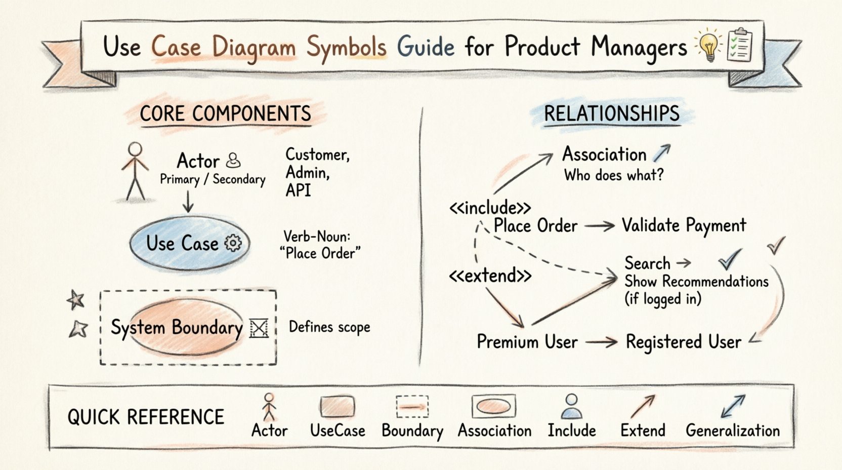
For quick reference, here is a structured overview of the symbols and their meanings.
| Symbol | Visual Shape | Meaning | Example |
|---|---|---|---|
| Actor | Stick Figure | External entity interacting with the system | Customer, Admin, API |
| Use Case | Oval | A specific function or goal of the system | Checkout, Login, Generate Report |
| System Boundary | Rectangle | Defines the scope of the system | Order Management System |
| Association | Solid Line | Communication link between Actor and Use Case | User clicks “Buy” |
| Include | Dashed Line + Arrow | Mandatory dependency on another use case | Login is required for Checkout |
| Extend | Dashed Line + Arrow | Optional addition to a use case under specific conditions | Apply Coupon during Checkout |
| Generalization | Solid Line + Triangle | Inheritance of behavior between actors or use cases | VIP Member extends Member |
Creating a Use Case Diagram is not just about drawing shapes. It requires strategic thinking about the product architecture and user experience. Follow these guidelines to ensure your diagrams add value.
Before drawing any lines, determine the boundaries of the current project. A diagram that tries to cover every possible feature of a company’s future roadmap will become unreadable. Focus on the specific release or sprint goals. Use the System Boundary to explicitly exclude features that are planned for later phases.
Use Cases should describe what the user achieves, not how they achieve it. Avoid designing screens or database tables in the diagram. For example, instead of “Click Button A”, use “Submit Form”. This keeps the diagram abstract and technology-agnostic.
Use the diagram as a conversation starter. Walk through the paths with engineers, designers, and business owners. Ask questions like: “Does the system handle this error case?” or “Is this actor necessary for this feature?”. This collaborative review often reveals gaps in logic before development begins.
Complexity leads to confusion. If a diagram has too many actors or use cases, consider splitting it into multiple diagrams. You might have a “User Registration” diagram and a “Order Management” diagram. This modularity makes maintenance easier as the product grows.
Even experienced practitioners can make mistakes when modeling systems. Being aware of these common errors will help you maintain high-quality documentation.
A Use Case Diagram is the starting point, not the destination. To turn these visuals into working software, you must connect them to detailed requirements.
Each oval in the diagram should have a corresponding text document. This description outlines the preconditions, the main success scenario, and alternative paths. This ensures that the visual shorthand is backed by detailed logic.
Many Product Managers prefer User Stories (As a [role], I want [goal], so that [benefit]) for agile tracking. You can map Use Cases to Epic-level stories. The diagram provides the structure, while the stories provide the iterative detail.
The relationships in the diagram, such as Include or Extend, translate directly to acceptance criteria. If a use case includes a validation step, the QA team needs to verify that specific step exists in every instance of the parent function.
The true power of a Use Case Diagram lies in its ability to facilitate discussion. It serves as a shared language between technical and non-technical teams.
When presenting these diagrams, focus on the flow. Walk through the diagram from the Actor’s perspective. “The customer logs in, then searches for items, then checks out.” This narrative approach makes the abstract symbols concrete.
Products evolve. Features get added, and others become obsolete. Your diagrams must reflect this reality.
Mastering the Use Case Diagram is a valuable skill for any Product Manager. It shifts the focus from implementation details to system behavior and user value. By understanding actors, use cases, boundaries, and relationships, you can define scope more accurately and reduce ambiguity in your requirements.
Remember that these diagrams are living documents. They should evolve with your product. Use them to facilitate conversations, validate logic, and ensure that everyone is aligned on what the system is supposed to do. With a solid grasp of these symbols, you are better equipped to guide your team through the complexities of software development.
Start by reviewing your current project’s diagrams. Identify any ambiguous connections or missing actors. Apply the principles outlined here to refine your documentation. This investment in clarity will pay dividends in efficiency and reduced rework as your product moves forward.