 Visual Paradigm Desktop |
  Visual Paradigm Online


Engineering complex systems requires more than just designing components; it demands a rigorous connection between intent and implementation. As systems grow in scope, incorporating software, hardware, mechanical structures, and operational logic, the risk of fragmentation increases. Model-Based Systems Engineering (MBSE) using SysML provides the framework to manage this complexity, but only if traceability is established correctly. This guide explores the structural patterns necessary to maintain a coherent system definition across diverse engineering domains.
Traceability in SysML is not merely a reporting feature; it is the backbone of verification and validation. Without strong links between requirements, design elements, and tests, the system architecture becomes a collection of isolated silos. Engineers must understand how to leverage the language to create robust connections that survive design iterations and domain hand-offs.
Before implementing patterns, one must understand the fundamental mechanisms within the language. SysML defines traceability primarily through the trace relationship, which can be applied between various elements. This relationship is distinct from standard structural or behavioral links.
Requirement Elements: These define what the system must do. They are the anchors of the traceability network.
Block Definition Diagrams (BDD): Define the physical and logical structure.
Internal Block Diagrams (IBD): Define the internal interfaces and flow.
Parametric Diagrams: Define constraints and mathematical relationships.
Verification Tests: Often represented as requirement types or separate verification requirements.
The core directive of traceability is to ensure that every requirement is satisfied by a design element and verified by a test case. This creates a closed loop of evidence. In multi-domain systems, this loop must span across different technical languages and engineering disciplines.
Different engineering questions require different traceability patterns. A blanket approach often leads to clutter or insufficient visibility. Below are the primary patterns used to structure system information.
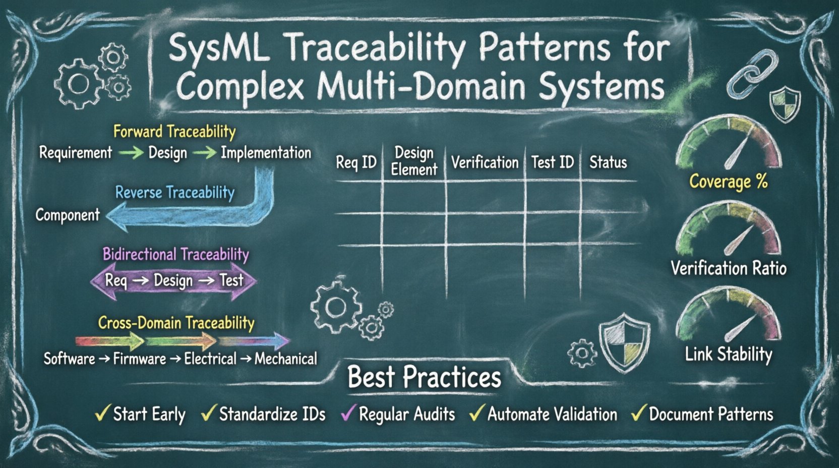
Forward traceability starts at the requirement and moves downstream toward the design and implementation. It answers the question: “What design elements satisfy this requirement?”
Direction: Requirement → Design → Implementation.
Use Case: Ensuring no requirement is left unimplemented.
Benefit: Prevents scope creep by confirming that every requested feature is addressed in the architecture.
Implementation: Use the deriveReqt or refine relationships to link requirements to blocks or use cases.
Reverse traceability moves upstream from the design element back to the originating requirement. It answers the question: “Why does this component exist?”
Direction: Design/Implementation → Requirement.
Use Case: Identifying redundant elements or dead code in the model.
Benefit: Supports change management by showing which requirements will be affected if a specific component is modified.
Implementation: Link blocks in an IBD back to specific requirements in the requirements diagram.
This pattern combines forward and reverse links to create a complete verification chain. It is the gold standard for safety-critical systems.
Direction: Requirement ↔ Design ↔ Test.
Use Case: Certification processes and regulatory compliance.
Benefit: Provides full coverage assurance for audits and safety cases.
In multi-domain systems, a software requirement must link to a hardware block, which links to a mechanical constraint. This pattern bridges the gap between different engineering languages.
Direction: Software Req → Firmware → Electrical Block → Mechanical Constraint.
Use Case: Cyber-physical systems where behavior depends on physical properties.
Benefit: Ensures that a software feature does not violate a physical limitation.
Organizing these patterns requires a structured approach. A matrix format is often the most effective way to visualize the relationships. The table below outlines the recommended columns for a comprehensive traceability matrix.
Requirement ID | Requirement Text | Source | Design Element ID | Design Element Type | Verification Method | Test Case ID | Status |
|---|---|---|---|---|---|---|---|
REQ-001 | System shall initiate startup sequence | Stakeholder | BLOCK-100 | Control Logic | Analysis | TEST-001 | Verified |
REQ-002 | Power consumption < 5W | Regulatory | PARAM-200 | Constraint | Simulation | TEST-002 | In Progress |
REQ-003 | Enclosure must withstand impact | Environmental | MECH-300 | Mechanical Part | Physical Test | TEST-003 | Approved |
Using a structured matrix ensures that no column is skipped during the review process. It forces the engineer to consider the verification method for every single requirement.
Complex systems rarely consist of a single engineering discipline. They involve interactions between software, electronics, mechanics, and operations. Each domain has its own lifecycle and terminology, making traceability difficult.
The most common friction point occurs where software meets hardware. A software requirement might state “The system shall respond within 50ms.” This is abstract. It must be traced to a hardware block that defines the processor speed and memory latency.
Pattern: Use a refine link from the software requirement to a functional block in the hardware definition.
Challenge: Timing constraints are often defined in parametric diagrams, while logic is defined in state machines.
Solution: Create a dedicated Interface Block that explicitly defines the timing properties and link the software requirement to this interface.
Mechanical constraints often dictate operational limits. If a mechanical arm has a maximum torque, the operational mode must reflect this limitation.
Pattern: Link operational use cases to the mechanical blocks they interact with.
Challenge: Operational requirements are often written in natural language, while mechanical models use mathematical constraints.
Solution: Translate operational limits into parametric constraints. Link the requirement directly to the equation in the parametric diagram.
Firmware often acts as the glue between high-level software and low-level physical signals. Traceability must ensure that a firmware driver correctly exposes the capabilities of the physical sensor.
Pattern: Use allocation relationships to assign firmware functions to specific hardware drivers.
Challenge: Firmware updates can occur without changing the physical hardware.
Solution: Maintain a versioning strategy on the traceability links. If the firmware changes but the requirement is met, update the link status rather than breaking the connection.
Implementing traceability is not without obstacles. Several common issues arise in complex environments. Recognizing these early allows for better planning.
Over time, as requirements change or designs evolve, links become stale. A requirement might be deleted, but the link remains pointing to a non-existent block.
Mitigation: Implement automated validation scripts that check for orphaned links during the build process.
Mitigation: Require a status flag on every link (e.g., Active, Deprecated, Pending).
Sometimes a requirement is too high-level to link to a single component, or a component is too detailed to link to a single requirement. This creates a many-to-many relationship that is hard to manage.
Mitigation: Decompose high-level requirements into lower-level functional requirements that align with system blocks.
Mitigation: Group multiple low-level components into a Composite Block and link to that instead.
Software engineers use different tools than mechanical engineers. They may not see the same traceability context.
Mitigation: Adopt a single source of truth model repository that supports integration with external domain tools.
Mitigation: Establish a common naming convention for all traceable elements across all domains.
Maintaining traceability requires discipline. It is not a one-time setup but a continuous activity.
Start Early: Define traceability requirements during the concept phase. Do not wait until the design phase to add links.
Standardize Naming: Use a consistent ID format (e.g., REQ-SYS-001, BLK-INT-001). This makes automated searching and reporting possible.
Regular Audits: Schedule quarterly reviews of the traceability graph. Check for broken links and orphaned requirements.
Automate Where Possible: Use built-in model validation features to flag inconsistencies. Avoid manual verification of links.
Document the Pattern: Create a standard operating procedure (SOP) that defines how links should be created, labeled, and maintained.
To ensure the traceability network is healthy, specific metrics should be tracked. These metrics provide visibility into the quality of the system definition.
This metric calculates the ratio of requirements that have at least one downstream link (design or test).
Goal: 100% of critical requirements must have coverage.
Measurement: (Linked Requirements / Total Requirements) × 100.
This measures the ratio of requirements linked to a verification method.
Goal: 100% of requirements must have a verification method assigned.
Measurement: (Requirements with Test/Analysis / Total Requirements) × 100.
This tracks the rate at which links are broken or changed over time.
Goal: Low rate of change indicates stable requirements.
Measurement: (Broken Links per Month / Total Links) × 100.
In safety-critical systems, a simple link is often insufficient. A hierarchical verification structure is required to demonstrate compliance at every level.
Level 1: System Requirement (e.g., “Vehicle shall stop in 100m”).
Level 2: Subsystem Requirement (e.g., “Brake system shall generate 500N force”).
Level 3: Component Requirement (e.g., “Hydraulic pump shall flow 10L/min”).
Level 4: Implementation Test (e.g., “Pump flow test result”).
This hierarchy ensures that a failure at the component level can be traced back to the system level requirement. It allows engineers to pinpoint exactly where a failure occurred in the chain of logic.
Change is inevitable. When a requirement changes, the impact analysis relies entirely on the traceability links.
Impact Analysis: When a requirement is modified, traverse all downstream links to identify affected blocks, interfaces, and tests.
Approval Workflow: Require approval from all impacted domains before changing a requirement. For example, changing a software requirement might require approval from the hardware team if it affects processor load.
Version Control: Maintain a history of the traceability graph. If a link is removed, the reason must be documented.
Real-world systems often pull data from external sources, such as supplier specifications or simulation results. SysML traceability should integrate these sources.
Supplier Requirements: Link internal requirements to external supplier documents using refine relationships.
Simulation Results: Attach simulation output files to parametric diagram constraints to prove the constraint is met.
Issue Tracking: Link defects or issues from a bug tracker directly to the requirement that caused them.
Large projects often involve multiple models for different subsystems. Traceability must be maintained across these model boundaries.
Model Import: Use reference packages to import blocks from one model into another while maintaining their ID and traceability links.
Interface Definition: Define strict interfaces between models. Traceability should not cross model boundaries through vague references.
Global Registry: Maintain a central registry of all requirements and their unique IDs to prevent duplication across models.
Building a robust traceability network is a strategic investment. It reduces the cost of change, improves verification confidence, and provides clear visibility into system health. By applying the patterns described above, engineers can manage the complexity of multi-domain systems without losing track of the original intent.
Success in this area depends on discipline, automation, and a clear understanding of the relationships between requirements, design, and verification. Treat the traceability graph as a living artifact that grows and evolves with the system. Regular maintenance and validation ensure that the model remains a reliable source of truth throughout the lifecycle of the project.