 Visual Paradigm Desktop |
  Visual Paradigm Online


In the landscape of complex systems engineering, safety is not an afterthought; it is a foundational requirement. As architectures become more interconnected and autonomous, the methods used to validate safety integrity must evolve. Model-Based Systems Engineering (MBSE) using the Systems Modeling Language (SysML) offers a robust pathway to integrate risk assessment directly into the design lifecycle. This guide explores how to construct a risk assessment framework within a SysML environment, ensuring compliance with industry standards without relying on specific proprietary tools.
By embedding hazard analysis and safety goals into the system model, engineers gain a single source of truth. This approach reduces silos, enhances traceability, and allows for early detection of design flaws. The following sections detail the architecture, methodology, and best practices for implementing this framework.
SysML provides a flexible and standardized syntax for describing system requirements, structure, behavior, and parametrics. Unlike traditional document-based approaches, SysML models are executable and analyzable. For safety-critical domains such as automotive, aerospace, and medical devices, this capability is crucial. The language allows engineers to define safety properties alongside functional requirements.
Key advantages of using SysML for safety-critical contexts include:
Integrating risk assessment requires a structured approach. It involves defining specific stereotypes or profiles within the SysML environment to represent risk entities. This ensures that risk data is treated with the same rigor as functional requirements.
The integration process typically follows these steps:
This structured mapping ensures that every safety constraint is accounted for during the design phase.
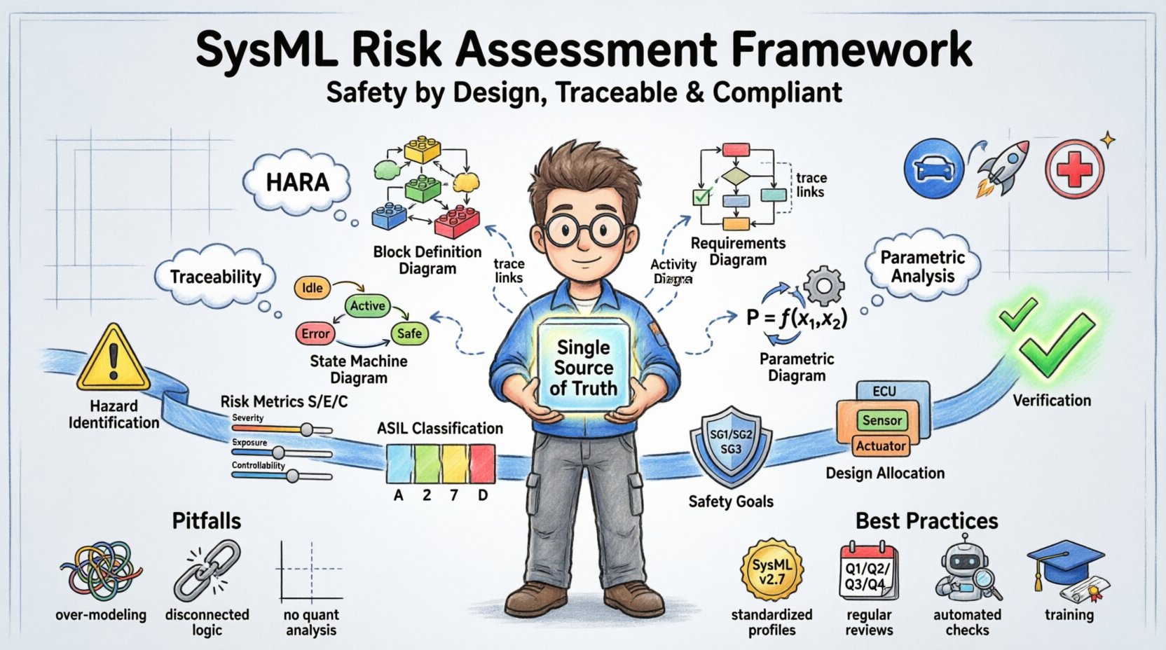
Different types of risk assessments map to different SysML diagrams. Understanding this correlation helps in organizing the model effectively.
| Risk Activity | Primary SysML Diagram | Key Elements |
|---|---|---|
| Hazard Analysis | Block Definition Diagram | Blocks, Hazard Stereotypes |
| Requirement Traceability | Requirements Diagram | Requirements, Trace Links |
| Functional Failure Analysis | Activity Diagram | Nodes, Flows, Decision Points |
| Quantitative Reliability | Parametric Diagram | Constraints, Variables, Equations |
| State-Based Safety Logic | State Machine Diagram | States, Transitions, Guards |
Hazard Analysis and Risk Assessment (HARA) is a critical process in safety engineering, particularly in automotive contexts governed by ISO 26262. In a SysML framework, HARA is not a separate document but a view within the model.
When performing HARA, engineers identify hazards associated with system functions. Each hazard is then analyzed for severity, exposure, and controllability. These attributes are stored as properties on the hazard element.
Steps for HARA Implementation:
This approach ensures that the ASIL allocation is visible and traceable throughout the architecture. It prevents safety goals from becoming disconnected from the actual design.
Once hazards are identified and risks assessed, safety goals are derived. A safety goal is a high-level constraint designed to reduce the risk to an acceptable level. In SysML, these goals are treated as top-level requirements.
The allocation of safety goals involves distributing the responsibility across system components. This is where the Block Definition Diagram becomes essential. Engineers define blocks representing subsystems and allocate safety constraints to them.
Key Practices for Allocation:
By maintaining these links, the model serves as a living document that proves compliance. Auditors can follow the trace from the hazard to the specific design element and its verification test.
Traceability is the backbone of any safety-critical process. It provides the evidence needed to demonstrate that safety requirements have been met. In SysML, traceability is achieved through relationships between elements.
Types of Traceability Links:
A robust traceability matrix can be generated from the model. This matrix shows the coverage of safety requirements across the design. If a hazard is modified, the model can be analyzed to identify which requirements and tests are affected.
Benefits of Automated Traceability:
While SysML offers powerful capabilities, improper usage can lead to model bloat and confusion. Several common pitfalls exist when implementing risk assessment frameworks.
1. Over-Modeling
Creating a model that is too detailed can obscure the safety logic. Focus on the elements that impact safety integrity. Do not model every minor feature if it does not affect the risk profile.
2. Disconnected Safety Logic
Ensuring safety requirements are linked to the functional model is critical. If safety logic exists in a separate document, traceability is broken. Always integrate safety constraints within the main system model.
3. Lack of Quantitative Analysis
Qualitative analysis is often insufficient for high-safety systems. Use parametric diagrams to perform quantitative reliability analysis where possible. This provides hard data to support safety claims.
4. Ignoring Evolution
Systems evolve. The risk assessment framework must support iterative development. Ensure the model is structured to allow for updates without breaking existing traceability links.
Best Practices for Success:
Different industries have specific risk considerations. SysML is extensible, allowing for the creation of domain-specific profiles. For example, functional safety in automotive differs from safety in medical devices.
Automotive Specifics:
Medical Device Specifics:
By tailoring the SysML profile to the domain, the model becomes more relevant and actionable. This customization allows for specific attributes that are unique to the industry standards.
Qualitative analysis tells you what can go wrong. Quantitative analysis tells you how likely it is to go wrong. SysML supports this through parametric diagrams.
These diagrams define mathematical constraints between variables. For risk assessment, this is used to calculate probabilities of failure on demand (PFD) or average probability of failure on demand (PFAD).
Key Components:
When solving these equations, the model can reveal if the current design meets the safety targets. If the calculated risk exceeds the threshold, the model highlights the bottleneck. This allows for optimization before physical prototyping.
Implementing a SysML-based risk assessment framework requires a phased approach. Rushing into modeling without a plan can lead to significant rework.
Phase 1: Definition
Define the safety profile and the specific risk categories to be modeled. Establish the naming conventions and standards for the project.
Phase 2: Pilot
Select a subsystem or a specific safety goal to model. Test the workflow from hazard identification to verification. Refine the process based on findings.
Phase 3: Expansion
Expand the model to cover the entire system. Integrate with other engineering domains such as software and hardware.
Phase 4: Maintenance
Establish a governance process for model updates. Ensure that changes are reviewed for safety impact.
Compliance with standards like ISO 26262, IEC 61508, and DO-178C is often mandatory. A SysML model serves as the evidence repository for these standards.
Key Compliance Areas:
The model provides the structure to manage this evidence. Reports generated from the model can be used directly in audit submissions, provided the model is well-structured and the data is accurate.
Building a safety-critical architecture is a responsibility that demands precision. The transition from document-based engineering to model-based engineering represents a significant shift in how safety is managed. By leveraging SysML, organizations can create a transparent, traceable, and analyzable safety case.
The framework described here is not a one-time setup but a continuous practice. It requires discipline to maintain the links and rigor to update the model as the system evolves. However, the payoff is a system that is safer by design, with clear evidence of compliance. The integration of risk assessment into the model ensures that safety is not an external check but an internal property of the architecture.
As systems become more complex, the tools used to manage that complexity must be equally sophisticated. SysML provides the necessary structure to handle this challenge. By following the guidelines outlined above, engineers can build frameworks that stand the test of time and scrutiny. The focus remains on clarity, traceability, and the relentless pursuit of safety integrity.