 Visual Paradigm Desktop |
  Visual Paradigm Online


Systems engineering projects often grow in complexity faster than the models used to represent them. As requirements expand and subsystems multiply, maintaining a monolithic SysML model becomes a significant challenge. This guide explores proven patterns for modularizing SysML models to enhance reusability, maintainability, and clarity. By adopting structured approaches, engineers can isolate concerns, streamline validation, and ensure that design components remain adaptable across different project lifecycles. 🔧
When a system model encompasses the entire lifecycle from requirements to architecture and verification, it risks becoming a tangled web of dependencies. Without intentional structure, changes in one area can ripple unpredictably through the entire model. This phenomenon is often referred to as high coupling in software engineering, and it applies equally to systems modeling.
Key issues associated with unstructured SysML models include:
Modularization addresses these issues by partitioning the model into logical units. This allows teams to focus on specific subsystems without the noise of the entire system definition. 🧩
Before diving into specific patterns, it is essential to understand the foundational constructs of the SysML language that support modularity. The primary mechanism for organizing content is the Package. Packages act as namespaces, grouping related elements together.
Every element in a SysML model must be uniquely identifiable. Packages provide a hierarchy that resolves naming conflicts. When a package is imported into another, its contents become available within the importing context, but the ownership remains with the source.
Blocks represent the physical or logical components of the system. Encapsulating behavior and structure within a block definition allows it to function as a distinct unit. This is crucial for reuse, as a block can be instantiated multiple times across different diagrams.
Interfaces define the interaction points of a component. By separating the interface definition from the implementation, you allow different implementations to satisfy the same contract. This decoupling is the cornerstone of reusable design.
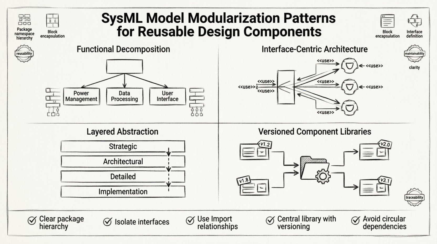
This pattern organizes the model based on the functions the system performs rather than the physical hardware. It aligns closely with the System Architecture Viewpoint.
When applying this pattern, ensure that functional blocks are abstract enough to allow for multiple physical realizations. Avoid hardcoding specific part types at the top level of the decomposition. Instead, define the function first, then refine it into physical parts in lower-level packages.
In complex systems, the interaction between subsystems is often more critical than the subsystems themselves. This pattern prioritizes the definition of ports and flows.
This approach reduces coupling. If the Control Interface changes, only the blocks that depend on it need to be updated, provided the interface definition is maintained correctly. It creates a clear boundary between what a component does and how it does it. 🚀
Layered abstraction separates the model into levels of detail. This is particularly useful for large-scale systems where stakeholders have different concerns.
| Layer | Focus | Primary Diagrams |
|---|---|---|
| Strategic | System context and major boundaries | Block Definition, Use Case |
| Architectural | Subsystem interaction and interfaces | Internal Block, Sequence |
| Detailed | Component logic and parameters | State Machine, Activity |
| Implementation | Physical parts and code mapping | Internal Block, Parametric |
By maintaining distinct packages for each layer, you prevent model bloat. A stakeholder looking at the strategic layer does not need to see the detailed logic of a sensor controller. This improves clarity and reduces the cognitive load on users of the model.
To implement this effectively, use Refine Relationships to link elements across layers. For example, a high-level requirement in the Strategic layer can be refined into a detailed requirement in the Detailed layer. This maintains traceability without merging the content.
For organizations managing multiple projects, a shared library of validated components is invaluable. This pattern treats standard components as assets that are imported rather than re-created.
When managing libraries, strict versioning is required. Each version of a component package should have a clear identifier. This prevents conflicts where one project expects an older interface signature than another. Documentation regarding the version history should be included within the package metadata.
Modularization introduces new challenges regarding how modules interact. Managing these dependencies is critical to prevent circular references and broken links.
SysML offers specific relationships to manage connections between packages and elements:
To maintain integrity across modules, every requirement must trace back to a design element. Use the Trace relationship to link requirements to blocks. When modularizing, ensure that traceability links do not cross module boundaries unless absolutely necessary. If a trace must cross, use a stable reference (like a Requirement ID) rather than a direct model path, which might break if the package structure changes.
Once a modular structure is in place, it must be validated. Automated checks can help identify structural issues before they impact the engineering process.
Performing these checks periodically, such as during a model merge or a release cycle, ensures the model remains healthy. Many modeling environments support scripting or rule engines to automate these validations.
Even with a solid plan, implementation errors can occur. Being aware of common mistakes helps in avoiding them.
One of the primary goals of modularization is to minimize the impact of change. When a requirement changes, you need to know exactly which parts of the model are affected.
With a well-structured model, you can perform forward and backward tracing. If a block definition is modified, trace the Usage dependencies to see which other blocks consume it. If a requirement changes, trace the Refine and Verify relationships to find the design elements and verification tests involved.
This visibility is essential for risk management. It allows engineers to prioritize updates and assess the effort required for a change request. Without modularization, this analysis is often manual and prone to error.
Implementing these patterns requires discipline and adherence to a defined process. The following checklist summarizes the key actions for a successful modularization strategy:
By treating the model as a structured assembly of interchangeable parts, engineers can build systems that are robust and adaptable. This approach supports the dynamic nature of modern systems engineering, where requirements evolve and technologies shift. The investment in modularization pays dividends through reduced maintenance costs and higher confidence in the final system design. 🛠️