 Visual Paradigm Desktop |
  Visual Paradigm Online


In the landscape of modern Model-Based Systems Engineering (MBSE), the complexity of development projects continues to rise. Teams are often distributed across different locations, disciplines, and organizational boundaries. This fragmentation creates significant challenges when ensuring that subsystems work together seamlessly. The Systems Modeling Language (SysML) provides a standardized framework for describing these complex systems, but the language itself is only as effective as the patterns used to structure it. This guide examines specific SysML interface definition patterns designed to facilitate clear communication and robust integration between cross-functional teams. By establishing consistent modeling conventions, organizations can reduce ambiguity, minimize rework, and accelerate the verification process. 🛠️
At the core of any large-scale engineering effort is the interface. An interface defines the boundary between two components, specifying how they interact without revealing their internal workings. In a collaborative environment, these boundaries are not merely technical specifications; they are agreements between teams. When a software team interacts with a hardware team, or when a mechanical subsystem connects to an electrical one, the interface is the contract that governs the exchange of data, energy, or control signals. 📜
Without a standardized approach to defining these boundaries, several issues arise:
SysML addresses these challenges through specific diagram types and structural elements. The Block Definition Diagram (BDD) and the Internal Block Diagram (IBD) are the primary tools used to visualize these relationships. However, simply using the tools is not enough. Teams must adopt patterns that enforce clarity and separation of concerns. 🧩
Before diving into specific patterns, it is essential to understand the fundamental building blocks that support interface definition in SysML. These elements form the syntax upon which all collaboration patterns are built. Mastery of these concepts allows engineers to express intent precisely. 🔍
When teams collaborate, they often disagree on the granularity of these elements. Some prefer coarse-grained blocks to maintain independence, while others require fine-grained interfaces to manage detailed data exchange. A standardized pattern helps resolve these architectural disagreements early in the design phase. 📐
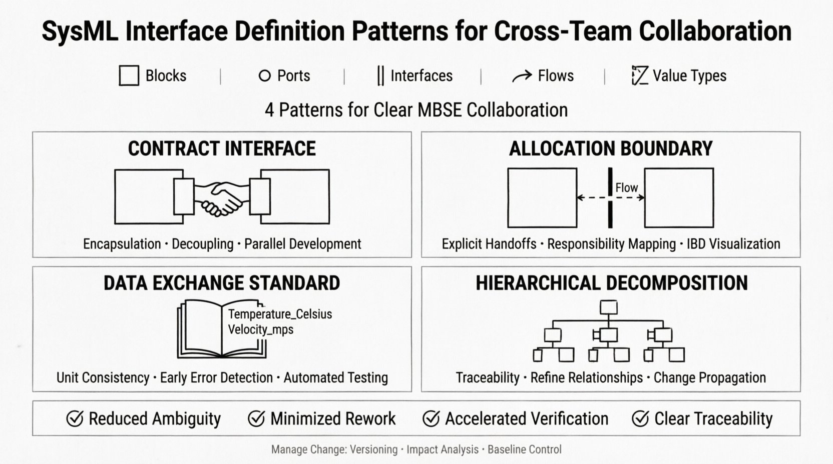
The Contract Interface pattern is the most fundamental approach to collaboration. It involves defining a dedicated interface block that encapsulates all the ports, operations, and value types required for communication. This block acts as a neutral ground where two teams agree on the exchange mechanism. 🤝
When implementing this pattern, a team should follow these steps:
Why does this work for cross-team collaboration? It enforces encapsulation. The hardware team can design the physical connector without knowing the software logic, provided the port types match. Conversely, the software team can design the logic without knowing the physical constraints, as long as the data flow requirements are met. This decoupling allows parallel development streams to proceed with confidence. 🚀
However, pitfalls exist. If the interface block becomes too complex, it becomes difficult to maintain. If it is too simple, it may lack necessary constraints. The key is balance. Teams should review the interface definition regularly to ensure it remains stable. 🛑
Systems engineering often involves allocating functions to physical components. The Allocation Boundary pattern ensures that the interface definitions align with the physical allocation of responsibilities. This is particularly useful when different teams are responsible for different physical domains, such as thermal management versus structural integrity. 🌡️🏗️
This pattern focuses on the Internal Block Diagram (IBD) to visualize how the allocated blocks interact. The rules for this pattern include:
By adhering to this pattern, teams avoid the common issue of “hidden dependencies.” A hidden dependency occurs when Team A assumes Team B will handle a specific signal, but Team B assumes Team A will handle it. The Allocation Boundary pattern makes these handoffs explicit in the model. This clarity is vital for verification activities. When a requirement states that a signal must be transmitted within 10 milliseconds, the model must show exactly where that signal originates and where it terminates. 📏
In modern systems, data is often the most critical asset. Different teams may use different units, naming conventions, or data structures. The Data Exchange Standard pattern addresses this by enforcing strict value types across all interface definitions. 📈
Implementation guidelines for this pattern are as follows:
This approach significantly reduces integration errors. If Team A defines a temperature value as degrees Celsius and Team B expects Kelvin, the system will flag a mismatch during model validation. This early detection saves significant time during physical prototyping. Furthermore, standardizing value types facilitates automated testing. Scripts can read the value type definitions and generate test cases automatically, ensuring that data integrity is maintained throughout the development lifecycle. ⚙️
It is important to note that this pattern requires discipline. Teams must resist the urge to create ad-hoc types for specific use cases. All custom types must be added to the central library and reviewed by a governance board. This ensures the library remains clean and usable. 📚
Complex systems are rarely monolithic. They are composed of subsystems, which are composed of sub-subsystems. The Hierarchical Decomposition pattern ensures that interface definitions propagate correctly down the hierarchy. This is essential for managing scope and preventing interface explosion. 📉
Key principles for this pattern include:
Without this pattern, a high-level requirement might be lost in translation as it moves down the hierarchy. A top-level requirement might state “The system shall provide power,” but the subsystem level might forget to define the power port. Hierarchical decomposition ensures that every level of the system maintains a consistent view of its external dependencies. This traceability is critical for certification and safety compliance. ✅
To assist in selecting the appropriate pattern for your project, consider the following comparison table. This highlights the strengths and limitations of each approach in a collaborative context. 📊
| Pattern | Primary Use Case | Strength | Limitation |
|---|---|---|---|
| Contract Interface | General component interaction | Clear encapsulation and decoupling | Can become complex if overused |
| Allocation Boundary | Physical domain handoffs | Explicit responsibility mapping | Requires strict governance of boundaries |
| Data Exchange Standard | Data-heavy systems | Prevents unit and type mismatches | Requires upfront library definition |
| Hierarchical Decomposition | Large scale systems | Maintains traceability down levels | Complexity in managing inheritance |
Collaboration is not a one-time event; it is an ongoing process. As requirements evolve, interface definitions must change. Managing these changes across teams is one of the most difficult aspects of MBSE. A change in one team’s model can break another team’s model if the interface is not versioned correctly. 📅
To manage this effectively, teams should adopt the following practices:
This discipline prevents the “moving target” syndrome, where requirements change so frequently that development cannot keep pace. By treating interfaces as stable contracts that evolve in controlled increments, teams can maintain momentum while still adapting to new needs. 🛡️
Adopting these patterns requires more than just technical knowledge; it requires cultural alignment. Here are some best practices to ensure successful implementation across your organization. 🌟
These practices foster a culture of quality and collaboration. They shift the focus from individual ownership to system ownership. When everyone contributes to the stability of the interface library, the entire system benefits from increased reliability. 🏆
The ultimate goal of defining interfaces is to ensure the system meets its requirements. Validation and Verification (V&V) activities rely heavily on the clarity of these definitions. If the interface is ambiguous, the test cases will be ambiguous. 🔬
To align V&V with interface patterns:
This alignment creates a closed loop of quality. The model drives the tests, and the tests validate the model. This reduces the risk of integration failure during physical testing phases. By catching errors in the model, teams save significant resources in the field. 💰
Even with the best intentions, teams often fall into common traps when defining SysML interfaces. Awareness of these pitfalls can help teams avoid them. ⚠️
By recognizing these risks early, project managers can allocate appropriate resources to prevent them. Regular audits of the interface library can help identify over-engineering or siloed modeling before they become critical issues. 🔎
The landscape of systems engineering continues to evolve. As systems become more connected and autonomous, the role of interface definition will become even more critical. Emerging trends such as digital twins and continuous integration for systems engineering will rely heavily on the robust patterns discussed in this guide. 🔮
Teams should remain flexible in their approach. While these patterns provide a strong foundation, they must be adaptable to new technologies. The core principle remains the same: clear, standardized, and traceable definitions of how systems interact. By maintaining this focus, organizations can continue to deliver complex systems successfully, regardless of the tools or methodologies used. 🌍
Effective collaboration in systems engineering depends on the quality of the definitions that bind teams together. SysML interface definition patterns provide the structure needed to manage this complexity. By adopting the Contract Interface, Allocation Boundary, Data Exchange Standard, and Hierarchical Decomposition patterns, teams can reduce ambiguity and accelerate development. 🏁
Remember that these patterns are tools, not rules. They should be tailored to the specific needs of the project and the organization. The goal is not just to create a model, but to create a shared understanding. When every team speaks the same modeling language, the system speaks louder. 🗣️