 Visual Paradigm Desktop |
  Visual Paradigm Online


Modern engineering systems are no longer siloed collections of parts. They are complex ecosystems where mechanical, electrical, software, and systems engineering converge. This convergence creates a challenge: how do diverse teams speak the same language while maintaining their specific expertise? Systems Modeling Language (SysML) offers a structured approach, but alignment across domains requires deliberate patterns. This guide outlines the essential strategies for integrating heterogeneous engineering teams using model-based systems engineering principles. We focus on practical alignment mechanisms that reduce friction and enhance traceability without relying on proprietary tool features.
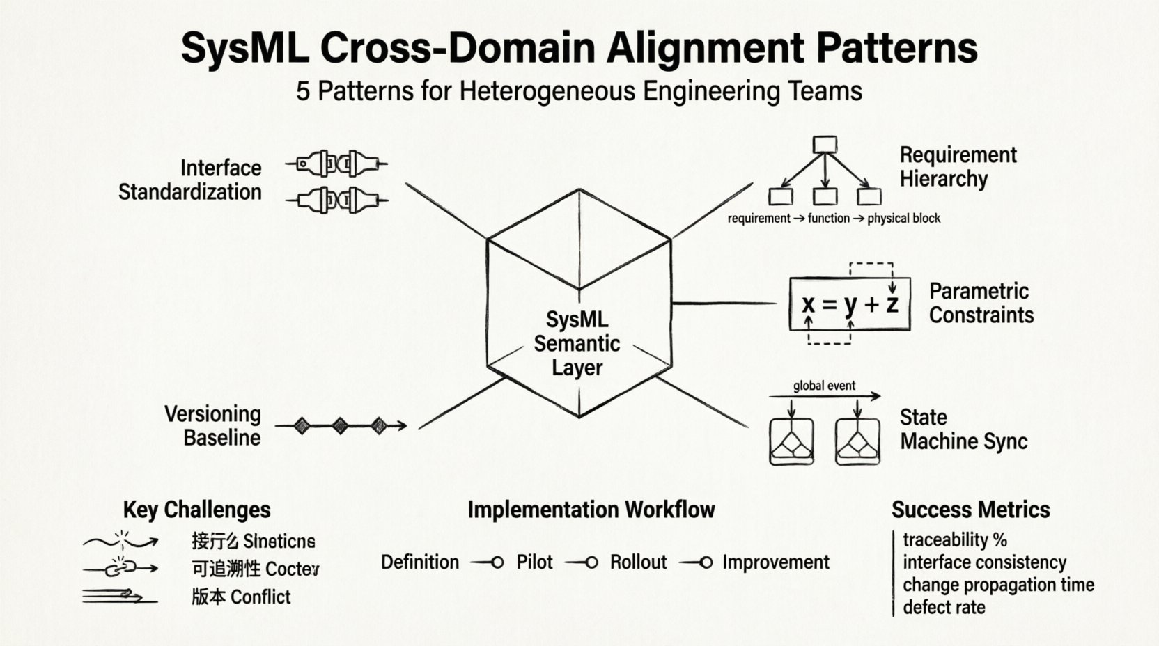
Heterogeneous teams operate with different mental models, terminologies, and lifecycle expectations. A software engineer thinks in algorithms and logic flows. A mechanical engineer thinks in tolerances and materials. A systems engineer thinks in requirements and interfaces. When these views collide without a structured integration method, errors propagate late in the lifecycle. SysML acts as the shared semantic layer, but raw modeling is insufficient. We need specific patterns to ensure that a definition in one domain maps correctly to another.
Without alignment, the following issues frequently arise:
To mitigate these risks, we must adopt alignment patterns that standardize how information is exchanged between disciplines. These patterns are not about enforcing a single tool; they are about defining a consistent modeling contract.
The most critical point of contact between domains is the interface. Misunderstood interfaces are the leading cause of integration delays. In SysML, this is managed through Block Definition Diagrams (BDD) and Internal Block Diagrams (IBD). The pattern involves strict rules for how ports and flow ports are defined and consumed.
When a hardware team defines a power bus, the software team must consume that exact definition. The pattern requires a review process where interface definitions are signed off by all consuming domains before the design phase proceeds. This creates a contract that is independent of any specific software tool.
Requirements are the source of truth for what the system must do. However, requirements often sit in one repository while the model sits in another. The alignment pattern focuses on how requirements are decomposed into functional and physical blocks.
For heterogeneous teams, this hierarchy acts as the bridge. The software team maps code modules to functional blocks. The hardware team maps components to physical blocks. Both must trace back to the same requirement node. This creates a unified view of scope across disciplines.
Engineering analysis often requires mathematical constraints. Performance, mass, power, and thermal limits are critical across all domains. SysML Parametric Diagrams provide the mechanism for sharing these constraints. The challenge is ensuring that the parameters defined in the model are consistent with the analysis tools used by specific teams.
When a mechanical team defines a mass constraint, the electrical team should be able to reference that variable in their power budget. This pattern ensures that trade-off studies are performed on consistent data. It prevents the scenario where the software team optimizes for performance while the hardware team optimizes for cost, resulting in an unbalanced system.
Behavioral modeling is often where the most confusion occurs. State machines describe the logic of the system. Software engineers often use UML or code-centric state diagrams, while systems engineers use SysML. Aligning these views is crucial for understanding system dynamics.
This pattern is particularly useful for embedded systems where the boundary between firmware and hardware logic is blurred. By synchronizing state machines, teams can verify that the system responds correctly to all inputs across the lifecycle.
Models evolve. Changes in one domain can invalidate assumptions in another. Managing this evolution requires a robust versioning strategy. The pattern focuses on how baselines are created and how changes are propagated.
Effective versioning ensures that a team can roll back to a stable state if a change causes integration issues. It also allows for parallel development streams where teams can work on different features without blocking each other.
Even with patterns, challenges remain. The following table outlines common friction points and the corresponding alignment strategy.
| Challenge | Root Cause | SysML Alignment Pattern |
|---|---|---|
| Requirement Drift | Requirements updated in isolation | Centralized Requirement Package with Review Gate |
| Interface Mismatch | Port types not standardized | Interface Definition Standardization Pattern |
| Traceability Breaks | Links lost during migration | Requirement Decomposition Hierarchy Pattern |
| Analysis Inconsistency | Different parameter definitions | Parametric Constraint Sharing Pattern |
| Behavioral Confusion | Local event definitions | State Machine Synchronization Pattern |
Adopting these patterns requires a shift in workflow. It is not just about changing the model; it is about changing the collaboration process. The following steps outline a typical implementation path.
Patterns alone do not guarantee quality. Governance ensures that the patterns are followed. This involves regular model reviews and audits. The goal is to maintain the integrity of the model as a single source of truth.
Quality assurance should be automated where possible. Scripts can check for orphaned requirements or missing interface types. This reduces the manual burden on engineers and allows them to focus on design.
How do you know the alignment patterns are working? You need metrics. The following key performance indicators (KPIs) help measure the effectiveness of the alignment strategy.
Tracking these metrics over time provides insight into whether the team is moving towards better alignment. A decreasing defect rate and increasing coverage indicate success. If metrics stagnate, the patterns may need adjustment.
Heterogeneous teams often use different tools. Some may prefer open standards, while others rely on specific ecosystems. The alignment pattern focuses on data exchange rather than tool homogeneity.
The goal is to ensure that the data remains valid regardless of the tool used to view it. This prevents vendor lock-in and allows teams to choose the best tools for their specific domain.
Aligning heterogeneous engineering teams is a continuous process. It requires discipline, communication, and a shared commitment to the model as the central artifact. The patterns outlined here provide a framework for achieving this alignment without mandating a specific technology stack. By focusing on interfaces, requirements, constraints, and behaviors, teams can reduce friction and improve system quality.
Success in SysML alignment comes from consistency. When every team follows the same rules for defining interfaces and tracing requirements, the complexity of the system becomes manageable. This approach enables teams to scale their engineering efforts while maintaining control over the system architecture.
Start small. Pick one pattern and apply it to a subsystem. Measure the results. Then expand. This iterative approach allows teams to adapt the patterns to their specific context while maintaining the core principles of alignment and traceability.