 Visual Paradigm Desktop |
  Visual Paradigm Online


Engineering complex systems requires a structured approach to manage increasing complexity. As systems grow in scope, spanning multiple domains and disciplines, traditional documentation methods often fail to maintain coherence. Model-Based Systems Engineering (MBSE) addresses this challenge by creating a digital twin of the system architecture. Within this framework, Systems Modeling Language (SysML) provides the standardized syntax for describing system structures, behaviors, and constraints. This guide details the architecture synthesis workflow, focusing on how to integrate disparate subsystems into a cohesive whole using rigorous modeling techniques.
Architecture synthesis is not merely drawing diagrams; it is the logical process of defining how components interact to satisfy high-level requirements. This process demands precision in defining interfaces, allocating functions, and ensuring traceability from concept to implementation. The following sections explore the workflow phases, diagrammatic representations, and strategies for maintaining integrity throughout the development lifecycle.
Before initiating synthesis, one must understand the core purpose of the model. The goal is to reduce ambiguity and risk before physical prototypes are built. In a complex integration scenario, multiple teams often work on different subsystems simultaneously. A shared architecture model acts as the single source of truth. This shared context ensures that changes in one area are immediately reflected across all related views.
The synthesis workflow relies on several key principles:
Without these principles, the model becomes a collection of disconnected diagrams. The synthesis workflow binds them together into a logical narrative that describes the system’s operation.
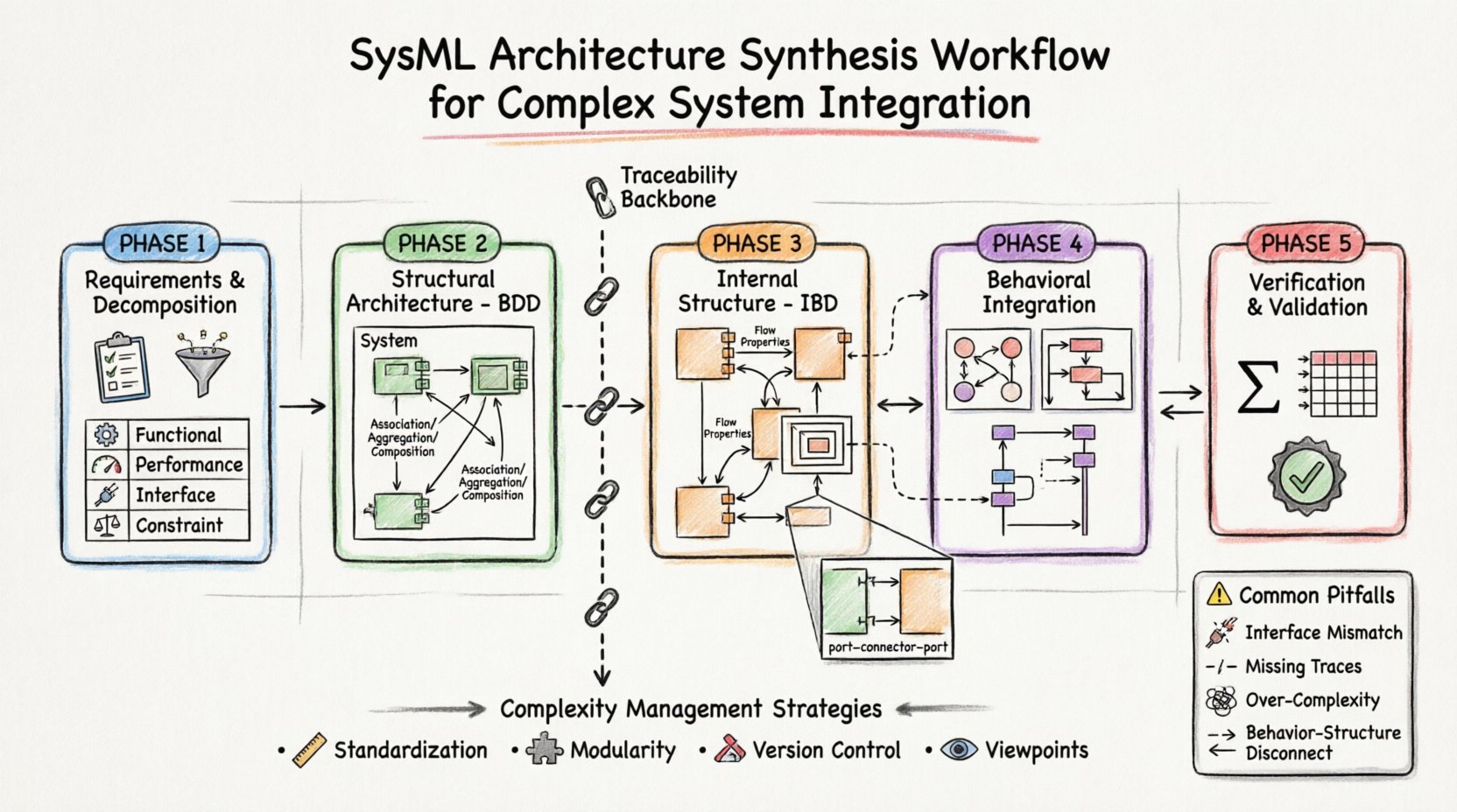
The synthesis process begins with requirements. A robust architecture cannot be synthesized from vague or incomplete needs. The primary activity in this phase involves refining high-level stakeholder needs into technical requirements. This is often represented using the Requirement diagram in SysML.
Key activities during this phase include:
It is critical to distinguish between user needs and engineering requirements. User needs describe what the system should achieve from an operational perspective. Engineering requirements define the technical specifications necessary to fulfill those needs. The synthesis workflow bridges this gap by allocating these engineering requirements to specific system blocks.
| Requirement Type | Focus | Example |
|---|---|---|
| Functional | What the system does | The system must process 1000 packets per second. |
| Performance | How well it performs | Latency must be under 50ms. |
| Interface | How it connects | Must use ISO-8859-1 protocol. |
| Constraint | Limitations | Weight must not exceed 5kg. |
Proper decomposition ensures that no requirement is left orphaned. Each requirement must trace to at least one design element. If a requirement cannot be allocated, it indicates a gap in the architecture that must be addressed before proceeding.
Once requirements are defined, the structural architecture is developed using Block Definition Diagrams (BDD). The block is the fundamental unit of structure in SysML. It represents a system component, which can be a single part or a composite of other parts.
The synthesis process in the BDD involves:
When defining blocks, it is essential to separate the interface from the implementation. The interface defines what a block exposes to the outside world. The implementation defines how the block achieves its function. This separation allows for flexibility; the internal logic of a subsystem can change without affecting the rest of the architecture, provided the interface remains constant.
Relationships between blocks are critical for synthesis. The Association relationship indicates a connection. The Aggregation relationship indicates a whole-part relationship where parts can exist independently. The Composition relationship implies a strong lifecycle dependency. Choosing the correct relationship type ensures the model accurately reflects the physical reality of the system.
While the BDD defines the parts, the Internal Block Diagram (IBD) defines how they are connected. This is the core of the integration workflow. The IBD shows the internal structure of a specific block, revealing the flow of information and material between its components.
Key elements in the IBD include:
During synthesis, the architect must ensure that every required interaction is represented by a connector. Missing connectors often indicate integration gaps. Furthermore, the direction of data flow must be clear. SysML distinguishes between flow direction and reference direction. Confusing these can lead to logical errors in the simulation or analysis phase.
A common challenge in IBD synthesis is managing complexity. As the number of blocks increases, the diagram can become cluttered. To mitigate this, architects should use nested IBDs. This allows for the hiding of internal details of a subsystem while maintaining the view of the top-level system. This hierarchical approach keeps the model manageable and readable.
Structure alone does not describe how the system behaves. The synthesis workflow must integrate behavioral models to ensure the system operates correctly over time. SysML offers several diagram types for behavior, including State Machine Diagrams, Activity Diagrams, and Sequence Diagrams.
The integration process involves mapping structural elements to behavioral events. For example, a specific port on a block might trigger a state transition. An activity diagram might describe the logic executed when data flows through a connector.
Key activities in this phase include:
It is vital to ensure consistency between structure and behavior. If a port is defined in the IBD but never used in the State Machine, it represents dead code or an unused interface. Conversely, if a behavior requires a port that does not exist in the structure, the model is incomplete. The synthesis workflow must iteratively check these alignments.
| Diagram Type | Primary Use Case | Integration Focus |
|---|---|---|
| State Machine | Control Logic | Triggering events from ports |
| Activity | Process Logic | Flow of data and control |
| Sequence | Temporal Order | Message exchange timing |
By linking behavior to structure, the model becomes a simulation-ready artifact. This allows engineers to test the logic before physical components are available. It reduces the risk of finding integration errors late in the development cycle.
Synthesis is not complete until the architecture is verified against requirements. Verification asks: “Did we build the system right?” Validation asks: “Did we build the right system?” SysML supports this through Parametric Diagrams and Constraint Blocks.
Parametric Diagrams allow for the definition of equations and relationships between parameters. This is essential for performance analysis. For example, if a subsystem has a power consumption requirement, the parametric model can calculate if the power supply block meets that demand based on the load requirements.
Validation is often achieved through traceability matrices. A traceability matrix links requirements to design elements and verification activities. If a requirement cannot be verified, it remains unvalidated. The synthesis workflow must ensure every requirement has a corresponding verification path.
Common verification activities include:
As systems grow, the number of model elements increases exponentially. Managing this complexity is a primary challenge in architecture synthesis. Without strict discipline, the model becomes unmanageable. The following strategies help maintain control:
Traceability is the backbone of integration. It ensures that changes in requirements propagate to the design. In a complex system, a change in one subsystem can ripple through the entire architecture. Automated traceability checks can identify these impacts quickly. This prevents “siloed” engineering where one team changes a parameter without realizing it breaks another team’s design.
Even with a defined workflow, pitfalls exist. Recognizing them early can save significant time and resources. Below are common issues encountered during SysML synthesis.
| Pitfall | Consequence | Mitigation Strategy |
|---|---|---|
| Interface Mismatch | Data corruption or failure | Define strict data types on ports |
| Missing Traces | Unverified requirements | Enforce traceability rules |
| Over-Complexity | Model becomes unreadable | Use hierarchical decomposition |
| Behavior-Structure Disconnect | Simulation errors | Review IBD and State Machines together |
Another frequent issue is the “big bang” integration attempt. Trying to connect all subsystems at the very end of the project is risky. The synthesis workflow encourages incremental integration. Subsystems should be integrated and verified in stages. This isolates issues to specific subsystems rather than the entire architecture.
Just as code requires testing, models require quality assurance. This involves checking the model for syntax errors, logical consistency, and completeness. Automated checks are often available within modeling environments. These checks can verify that all ports are connected, all requirements are traced, and all parameters are defined.
Manual reviews are also necessary. A peer review of the architecture can catch logical errors that automated tools miss. Reviewers should focus on the clarity of the design and the robustness of the interfaces. They should ask: “If this component fails, does the system degrade gracefully?” This type of question drives resilience into the architecture.
The field of systems modeling continues to evolve. Emerging trends focus on increasing automation and interoperability. The ability to exchange models between different tools is becoming more critical. Open standards ensure that the architecture synthesis workflow is not dependent on a single vendor.
Additionally, the integration of simulation tools directly into the modeling environment is improving the fidelity of the analysis. This allows for more accurate predictions of system performance before physical realization. The synthesis workflow must adapt to these tools, ensuring that the model remains the primary reference point even as simulation capabilities expand.
Ultimately, the goal of the architecture synthesis workflow is to deliver a system that works as intended. By following a disciplined process, leveraging the full power of SysML, and maintaining rigorous quality standards, engineering teams can manage complexity and deliver high-value solutions. The model serves as the blueprint for success, guiding the integration from concept to reality.