 Visual Paradigm Desktop |
  Visual Paradigm Online


Systems engineering involves navigating complex interdependencies where failure is not an option. Senior engineers understand that risk is inherent in the architecture of modern systems. Moving away from static documents to dynamic models allows for deeper analysis. SysML, the Systems Modeling Language, provides the necessary constructs to formalize risk management. This guide explores how to leverage SysML for architecture risk mitigation without relying on proprietary tooling specifics.
Effective risk modeling requires a shift in perspective. It is not merely about listing potential failures. It is about embedding risk logic into the system structure itself. This approach enables automated verification and clearer traceability. Engineers can visualize how a risk in one component propagates through the entire system.
Traditional risk registers exist in spreadsheets. They are disconnected from the design. When the design changes, the risk register often becomes outdated. SysML bridges this gap. By integrating risk elements into the model, the data remains synchronized with the architecture.
Key benefits include:
Senior engineers value precision. Spreadsheets offer flexibility but lack structural integrity. SysML models enforce relationships. A risk attached to a block cannot be deleted without addressing the block dependency. This structural rigidity ensures that mitigation strategies are not overlooked during design iterations.
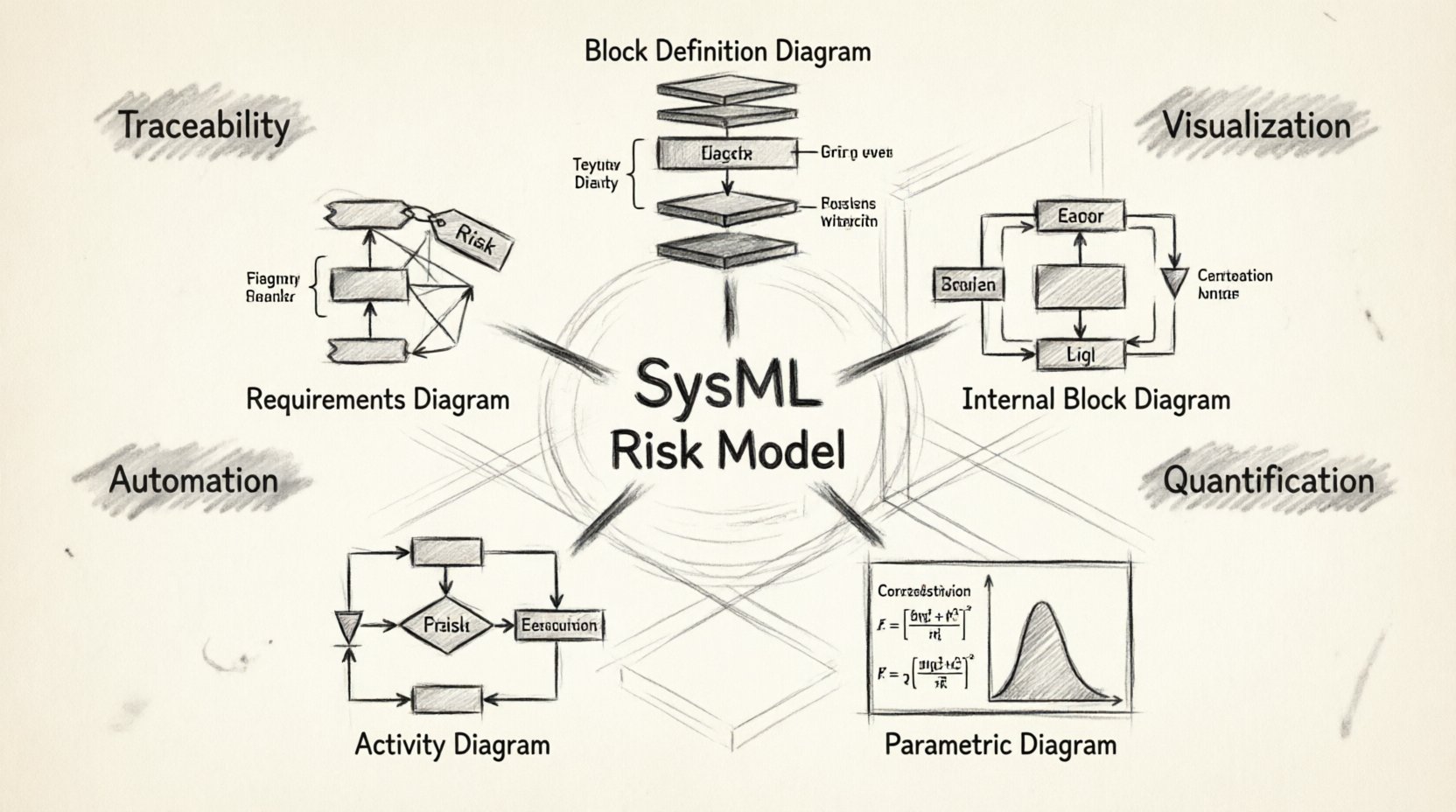
Different types of risks require different modeling constructs. A senior engineer selects the diagram type based on the nature of the threat. Some risks are structural, while others are behavioral or quantitative.
| Diagram Type | Primary Use Case | Risk Aspect Addressed |
|---|---|---|
| Requirements Diagram 📝 | Linking risk requirements to system goals | Compliance and Safety Standards |
| Block Definition Diagram (BDD) 🧱 | Defining component structure and interfaces | Structural Failure and Interfaces |
| Internal Block Diagram (IBD) 🔗 | Showing internal connections and flows | Data Flow and Signal Interference |
| Parametric Diagram (PD) 📊 | Mathematical constraints and calculations | Performance Degradation and Probability |
| Activity Diagram 🔄 | Process flows and state changes | Operational Logic and Timing |
Every risk begins as a requirement. Some requirements define safety margins or performance thresholds. SysML requirements diagrams allow engineers to tag specific requirements with risk attributes.
When modeling these requirements, consider the following steps:
This structure ensures that every risk has a corresponding requirement. If the requirement is satisfied, the risk is mitigated. If the requirement is violated, the risk is active. This creates a closed loop of verification.
The Block Definition Diagram (BDD) defines the system hierarchy. It is the primary canvas for understanding where components reside. Structural risks often stem from how components are organized.
Common structural risks include:
To model these, engineers can use stereotypes to annotate blocks. For example, a block might be marked as critical infrastructure. Connectors between blocks can be tagged with failure modes. This visual annotation helps teams identify fragile points in the architecture without needing a simulation environment.
Senior engineers should focus on defining clear interfaces. Ambiguity in interface definitions is a primary source of risk. SysML enforces strict typing on ports and flows. This reduces the likelihood of integration errors later in the lifecycle.
While BDDs show structure, Internal Block Diagrams (IBD) show behavior within that structure. They depict how data, energy, or material flows between parts.
Flow risks are critical in complex systems. Examples include:
Modeling these flows allows engineers to trace the path of a potential failure. If a flow fails, which downstream blocks are affected? The IBD makes these dependencies explicit.
Use reference properties to link IBDs to BDDs. This maintains consistency. If a block definition changes, the internal flow diagram updates automatically. This synchronization is vital for maintaining an accurate risk profile.
Not all risks are binary. Some exist on a spectrum. Parametric Diagrams allow for mathematical modeling of risk factors. This is essential for probabilistic risk assessment.
Engineers can define equations that relate system parameters to risk levels. For instance, a temperature constraint might be linked to a failure rate equation. If the temperature exceeds a threshold, the model calculates the increased probability of failure.
Key steps for parametric modeling:
This quantitative approach moves risk management from intuition to calculation. It supports decision-making when trade-offs are necessary. If increasing load reduces reliability, the model quantifies the trade-off.
A risk model is only as good as its traceability. Engineers must verify that the risk model aligns with the physical system. SysML supports bidirectional traceability.
Traceability links include:
Verification ensures that the mitigation strategies work. Validation ensures that the right risks are being addressed. Both are necessary for a robust architecture.
Experience brings a nuanced understanding of risk. Senior engineers should apply these practices to maintain model integrity.
Use consistent naming conventions for risk types. Avoid generic terms like “Potential Issue.” Instead, use specific categories such as “Thermal Overload” or “Signal Latency.” Consistency improves searchability and analysis.
Break large systems into subsystems. Model risks at the subsystem level first. Then aggregate them at the system level. This prevents the model from becoming unmanageable. It also allows teams to focus on specific areas of concern.
Models change over time. Maintain version history for all risk-related elements. This allows engineers to revert to previous states if a new design introduces unforeseen risks. It also provides an audit trail for compliance.
Link risk models to test cases. When a risk is mitigated, a test should verify the mitigation. When a risk is identified, a test should detect it. This closes the loop between modeling and execution.
Not every element needs a risk model. Focus on high-risk areas. Modeling low-risk elements adds complexity without value. Prioritize based on impact and probability.
Risk mitigation often involves trade-offs. Reducing risk in one area might increase it in another. SysML supports trade-off analysis through constraints and requirements.
For example, adding redundancy reduces failure probability but increases weight and power consumption. Engineers must balance these factors. Use parametric diagrams to model the relationship between redundancy and weight.
Document the rationale for every trade-off. This documentation is crucial for future audits. It explains why a specific risk level was accepted.
Risk models are not static artifacts. They evolve as the system evolves. Lessons learned from testing should feed back into the model.
Update the model when:
Regular reviews ensure the model remains relevant. Senior engineers should schedule these reviews as part of the project lifecycle. They should not wait for a crisis to update the risk profile.
Models facilitate communication. A visual representation of risk is easier to understand than a text document.
Share models with stakeholders. Use them in design reviews. Visualizing risk helps non-technical stakeholders understand the implications of design decisions. This alignment is critical for project success.
Ensure that the model is accessible. Use standard formats that other tools can read. This prevents vendor lock-in and ensures long-term usability.
Systems engineering does not exist in a vacuum. Risk models must integrate with software, hardware, and operations engineering.
Software engineers need to know which requirements carry high risk. Hardware engineers need to understand thermal constraints. Operations teams need to know maintenance risks.
SysML provides a common language for these disciplines. By modeling risks in a shared environment, all teams work from the same source of truth. This reduces silos and improves overall system reliability.
How do you know if the risk model is working? Define metrics for effectiveness.
Track these metrics over time. They provide insight into the maturity of the risk management process. Use the data to identify areas for improvement.
The field continues to evolve. New standards and extensions are emerging. Engineers should stay informed about developments.
Potential trends include:
Preparing for these trends ensures long-term relevance. Invest time in learning new capabilities as they become available.
Implementing SysML for risk mitigation is a strategic decision. It requires commitment to modeling standards and discipline in maintenance. The effort pays off in reduced failures and clearer communication.
Key takeaways for engineers:
By following these principles, engineers can build systems that are robust and reliable. Risk mitigation becomes an integral part of the design process, not an afterthought. This approach defines modern systems engineering excellence.