 Visual Paradigm Desktop |
  Visual Paradigm Online


In modern software development, the divide between product strategy and engineering execution often leads to friction. Product teams define what needs to be built to solve user problems, while engineering teams determine how to build it securely and efficiently. When these two perspectives drift apart, the result is often scope creep, missed deadlines, and features that do not deliver value. To bridge this gap, organizations need a shared language that is visual, structured, and precise. Enter the Use Case Diagram. 📊
This guide explores how strategic alignment is achieved by leveraging Use Case Diagrams. We will examine the mechanics of these diagrams, how they facilitate communication, and the specific steps required to integrate them into your workflow. By adopting this approach, teams can ensure that the technical architecture directly supports the intended business outcomes.
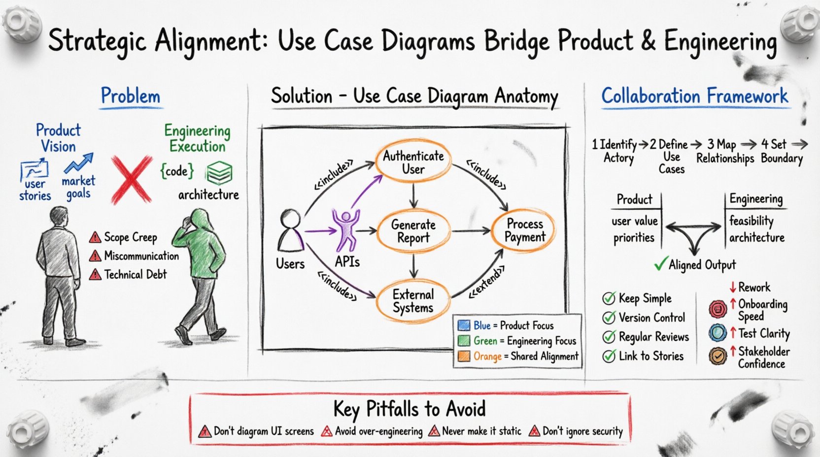
A Use Case Diagram is a visual representation of the interactions between a system and its external entities. It focuses on the what of the system rather than the how. This distinction is crucial for aligning high-level goals with technical implementation. Unlike detailed flowcharts that dictate logic paths, use case diagrams outline functional requirements from the perspective of the user.
Key components include:
When teams map these elements together, they create a blueprint that is readable by both technical and non-technical stakeholders. This shared visual aid reduces ambiguity and sets a clear baseline for development.
Misalignment often stems from differences in communication styles and priorities. Product managers focus on user needs and market timing, often describing features in narrative form. Engineers focus on data structures, latency, and system stability, often describing constraints in technical terms. Without a bridging mechanism, assumptions fill the gaps.
Common sources of friction include:
Using a Use Case Diagram forces clarity. It requires stakeholders to agree on who the actors are and what the system must do for them before writing a single line of code. This upfront investment prevents costly rework later.
These diagrams act as a contract between the product vision and the engineering reality. They translate business goals into functional specifications. When a product manager describes a new feature, the diagram captures it as a use case. When an engineer reviews it, they identify the necessary actors and system boundaries. This process creates a feedback loop that validates feasibility against intent.
Benefits of this approach:
Building a robust Use Case Diagram requires collaboration. It should not be a solo activity performed by one department. Follow this framework to ensure accuracy and buy-in.
Start by listing every entity that interacts with the system. Do not limit this to human users. External APIs, payment gateways, and monitoring systems are also actors. Categorize them to understand their authority and interaction level.
For each actor, list the goals they want to achieve. Frame these as verbs. Instead of “Login,” use “Authenticate User.” Instead of “Report,” use “Generate Monthly Sales Report.” This ensures the focus remains on the action and value provided.
Draw lines connecting actors to their use cases. If one use case is required for another, use an Include relationship. If a use case can optionally extend another under specific conditions, use an Extend relationship. These logical connections clarify dependencies.
Draw a rectangle around the use cases. Everything inside is part of the system. Everything outside is external. This helps engineers understand where their code ends and where external dependencies begin.
Understanding the specific contributions of each team helps streamline the process. The table below outlines how each group interacts with the diagram.
| Activity | Product Team Responsibility | Engineering Team Responsibility |
|---|---|---|
| Actor Definition | Identify user roles and external business entities. | Identify system interfaces and technical dependencies. |
| Use Case Selection | Prioritize based on user value and market strategy. | Validate based on technical feasibility and cost. |
| Relationship Mapping | Define business logic flows and exceptions. | Define data flows and API contracts. |
| Validation | Ensure the diagram matches user stories. | Ensure the diagram matches architecture design. |
This matrix highlights that while the diagram is a shared artifact, the input from each side is distinct. The product side ensures utility; the engineering side ensures constructability.
To get the most out of this tool, teams must adhere to certain standards. Ad hoc diagrams often become obsolete quickly. Structured diagrams endure.
Even experienced teams make mistakes when designing these diagrams. Awareness of common errors can save significant time.
How do you know if this approach is working? Look for specific metrics that indicate improved synchronization.
Integration requires more than just drawing boxes. It requires changing how work is initiated.
During Planning: Use the diagram to scope the sprint. Ensure every story selected maps to a use case on the diagram. If a story does not map, question its necessity.
During Design: Engineers can use the diagram to identify system boundaries. They know exactly which components need to be built to support specific actors.
During Testing: QA testers use the diagram to generate test cases. Each use case represents a potential test scenario.
During Maintenance: When bugs occur, engineers can trace the issue back to a specific use case interaction to understand the context.
As systems grow, so does the complexity of the interactions. A monolithic system might have a single diagram, but a microservices architecture requires a different approach.
Subsystems: Break the system into logical modules. Create a high-level diagram for the entire platform and detailed diagrams for individual services.
External Systems: Clearly label external APIs and third-party integrations. This helps engineers identify where data leaves the secure boundary of the application.
Security Actors: Include security protocols as actors or use cases. For example, “Authenticate User” or “Authorize Access” should be explicit.
Strategic alignment is not a one-time event; it is a continuous practice. Use Case Diagrams provide the structure needed to maintain this alignment over time. By focusing on interactions rather than implementation details, product and engineering teams can speak the same language. This reduces friction, clarifies priorities, and ensures that the final product delivers the intended value.
Adopting this visual methodology requires discipline and consistency. However, the payoff in reduced rework, clearer communication, and higher quality output makes the effort worthwhile. Teams that invest in this shared visual language will find themselves better equipped to navigate the complexities of modern software development.
Start small. Pick a feature or a subsystem. Map the actors and the goals. Invite both product and engineering to review it. Iterate from there. The path to alignment is paved with clarity, and these diagrams are the tool to build it.