 Visual Paradigm Desktop |
  Visual Paradigm Online


System complexity continues to rise across aerospace, automotive, and defense sectors. Managing this complexity requires more than just documentation; it demands a structured approach to modeling. Model-Based Systems Engineering (MBSE) provides the framework, and SysML serves as the language. For senior engineers, the core challenge lies not in creating models, but in decomposing requirements effectively. This process bridges the gap between high-level stakeholder needs and detailed engineering specifications.
Effective decomposition ensures that every system function has a clear lineage. It allows teams to trace a requirement from its origin down to the physical component level. This guide outlines strategies for breaking down requirements within the SysML framework without relying on specific commercial tools. The focus remains on the structural logic and semantic relationships that drive successful system design.
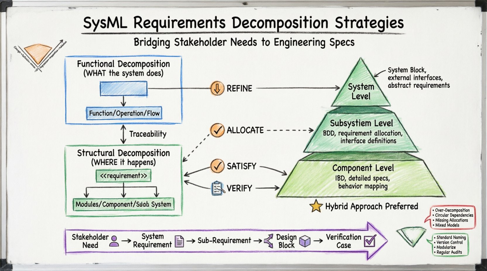
Requirements decomposition is the systematic breakdown of high-level system needs into manageable sub-requirements. In a traditional document-driven workflow, this often results in disconnected spreadsheets. In SysML, it creates a living model where relationships are explicit.
Senior engineers must distinguish between two primary types of decomposition:
The goal is to maintain bidirectional traceability. If a top-level requirement changes, the model should highlight every affected sub-requirement and component immediately. This reduces risk during the integration phase.
SysML defines specific relationship stereotypes that govern how requirements interact. Understanding these semantics is crucial for accurate modeling. Using the wrong relationship type can break traceability links.
This relationship connects a high-level requirement to a more detailed one. It establishes a hierarchical structure. For example, a requirement for “System Safety” refines into “Emergency Brake Activation.”
Allocation links a requirement to a structural element (a Block). It answers the question: “Which part of the system is responsible for this?”
This relationship is typically used when a lower-level component satisfies a higher-level system requirement. It often appears in the context of design verification.
This links a requirement to a test or verification method. It ensures that every requirement has a means of validation.
Senior engineers should approach structural decomposition in layers. A flat model is difficult to maintain. A layered model supports scalability.
At the top, define the System Block. This block represents the entire product or system under development. Requirements here are broad and stakeholder-facing.
Decompose the System Block into major Subsystems. Use Block Definition Diagrams (BDD) to define the composition.
Drill down into specific components within the subsystems. This is where detailed engineering specifications live.
| Approach | Best For | Complexity | Traceability |
|---|---|---|---|
| Sequential Decomposition | Linear processes | Low | Direct |
| Parallel Decomposition | Independent subsystems | Medium | Requires matrix |
| Hybrid Decomposition | Complex integrated systems | High | Integrated Model |
The Hybrid approach is generally preferred for complex engineering projects. It combines functional flow with structural allocation, ensuring both “what” and “where” are defined simultaneously.
Traceability is not just a checkbox; it is the backbone of the MBSE process. Without it, changes become unmanageable. In SysML, traceability is established through links, not spreadsheets.
A robust chain connects the following elements:
When a change occurs, the engineer must follow these links to assess impact. If a sensor specification changes, trace it back to the requirement it satisfies, then to the system requirement it supports. This prevents unintended consequences in other parts of the system.
Verification confirms that the product meets the specifications. Validation confirms that the product meets the stakeholder needs. SysML supports both through relationships.
Senior engineers should define the verification method at the time the requirement is created. This ensures that test planning happens early in the lifecycle.
Even experienced teams encounter issues when modeling requirements. Awareness of these pitfalls helps maintain model integrity.
Breaking requirements down too finely creates noise. If a requirement is so small it cannot be verified independently, it is likely unnecessary. Keep the granularity aligned with the verification capability.
Requirements should not depend on each other in a loop. Requirement A cannot rely on Requirement B if Requirement B relies on Requirement A. This creates logical paradoxes during implementation.
It is common to define a function but forget to allocate it to a block. This leads to “ghost functions” that exist in the model but have no physical owner.
Do not mix functional requirements directly into structural diagrams. Keep the functional analysis in Activity or Sequence Diagrams and the structural definitions in Block Definition Diagrams. Link them explicitly.
To ensure long-term success, senior engineers should adopt specific governance practices. These standards apply regardless of the software environment used.
The V-Model remains a standard framework for system development. SysML maps directly to the stages of the V-Model.
| V-Model Stage | SysML Activity | Output |
|---|---|---|
| Concept | Stakeholder Requirements Analysis | Stakeholder Requirements |
| System Definition | System Requirements Definition | System Requirements |
| Architecture Design | Logical System Design | Logical Architecture Blocks |
| Implementation Design | Physical System Design | Physical Components |
| Integration | Verification | Test Results |
| Validation | Validation | Operational Readiness |
Mapping these stages ensures that the model evolves alongside the project. It prevents the disconnect between the “as-designed” model and the “as-built” product.
Beyond basic decomposition, senior engineers can leverage advanced features to handle complexity.
Use Parameter Diagrams to define constraints on requirements. This is vital for performance requirements. You can define inputs, outputs, control factors, and noise factors.
For requirements involving state-dependent behavior, use State Machine Diagrams. This captures the logic of when a function is active.
Use Constraint Blocks to define mathematical relationships between parameters. This allows for automated checking of design feasibility.
Change is inevitable. A robust decomposition strategy makes change manageable.
Senior engineers must enforce strict configuration management. A requirement should not change without a review of its dependencies. This discipline prevents the “ripple effect” of errors.
Implementing these strategies requires discipline and a shift in mindset. It moves the team from documentation-centric to model-centric engineering. The benefits are substantial: reduced ambiguity, earlier detection of errors, and clearer communication.
For senior engineers, the role is to set the standard. Define the decomposition rules. Enforce the relationships. Ensure the model remains a source of truth. By adhering to these principles, the engineering team can navigate complexity with confidence.
The journey toward effective MBSE is continuous. As systems grow more complex, the need for rigorous decomposition grows with them. Stay focused on the relationships. Keep the traceability clear. Build the model to support the product, not the other way around.