 Visual Paradigm Desktop |
  Visual Paradigm Online


Creating a Data Flow Diagram (DFD) is a significant milestone in system analysis. It maps the movement of data through a system, defining how information is processed, stored, and transferred. However, a diagram that looks visually appealing is not necessarily functionally accurate. Validation is the critical phase where you verify that the diagram correctly represents the system requirements without logical errors. This process ensures that data flows are consistent, processes are balanced, and the structure supports the intended business logic.
Validation is not a single action but a disciplined review. It requires a methodical approach to check every element against established rules. By following a structured review process, you eliminate ambiguity and ensure that the diagram serves as a reliable blueprint for development and stakeholder communication. This guide outlines the comprehensive steps required to validate your DFD effectively, ensuring accuracy and consistency throughout the system design.
Before diving into the specific steps, it is essential to understand what validation achieves in the context of system design. Verification asks, “Are we building the product right?” Validation asks, “Are we building the right product?” In the context of DFDs, validation bridges the gap between abstract requirements and concrete system behavior.
A validated DFD ensures:
Skipping this phase often leads to costly rework during the development stage. Issues such as missing data flows or undefined data stores are expensive to fix once code is being written. A rigorous review process mitigates these risks early.
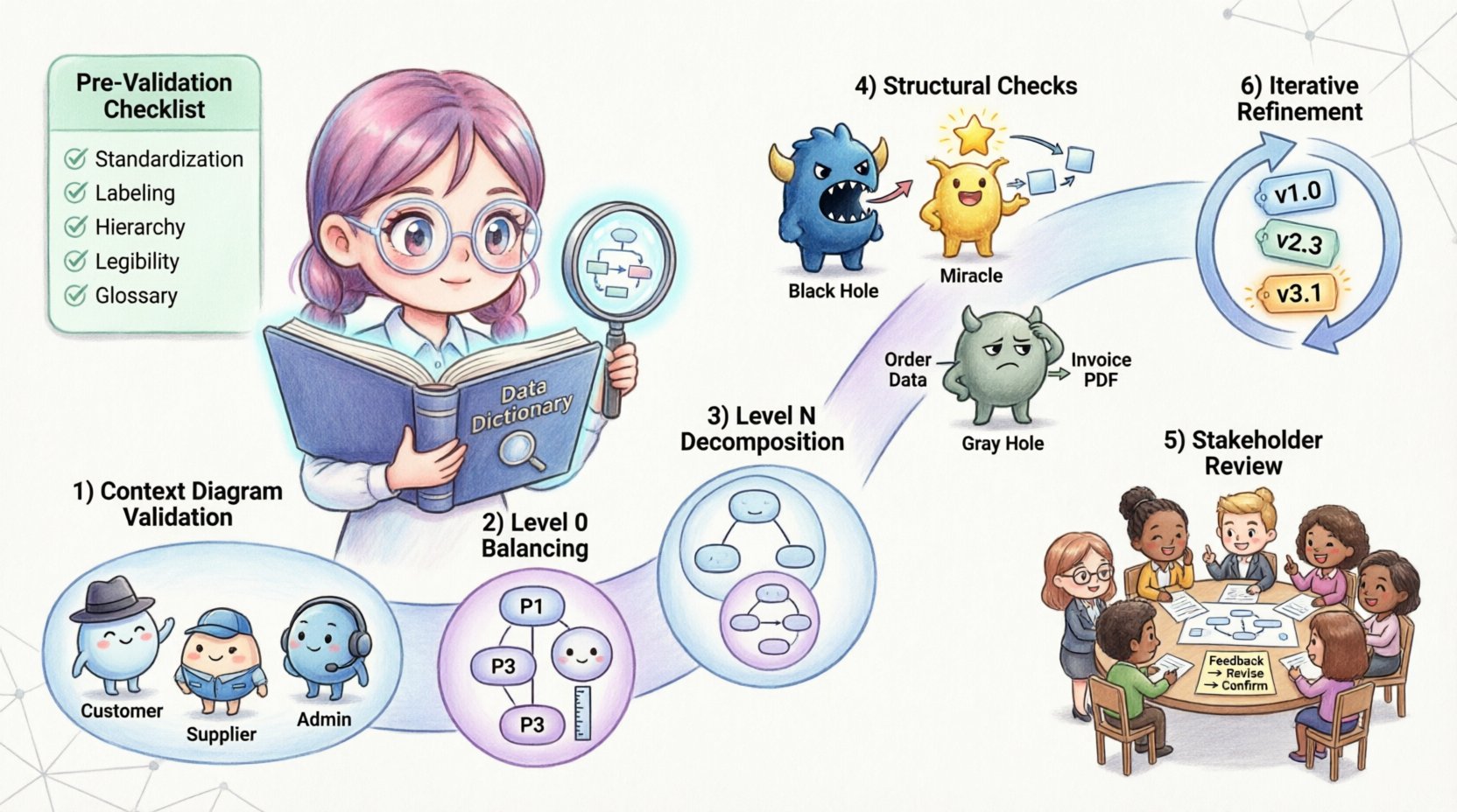
Before beginning the formal review, ensure the diagram is prepared for scrutiny. A cluttered or poorly organized diagram makes validation difficult. Use the following checklist to prepare your work:
The Context Diagram is the highest level of abstraction. It shows the system as a single process and its interaction with external entities. This is the first line of defense in validation.
External entities represent sources or destinations of data outside the system boundaries. Ensure that every entity shown is necessary and clearly defined. Ask the following questions:
The single process representing the system must contain all internal logic. Validate that no data flows cross the boundary without passing through this process. If data moves from one external entity to another without entering the system, it should not be shown on the Context Diagram, as it falls outside the scope.
Review every arrow connected to the central process. Each input must have a corresponding output or storage action. If a data flow enters the system but no data leaves, it may indicate a “Black Hole” process, where data disappears without purpose.
Level 0 DFD decomposes the single process of the Context Diagram into major subsystems. The most critical rule here is balancing. The inputs and outputs of the parent process must match the inputs and outputs of the child processes exactly.
For every data flow entering the Context Diagram process, there must be a corresponding data flow entering the Level 0 diagram. The same applies to outputs. This is known as data conservation. If the Context Diagram shows “Customer Order” entering the system, the Level 0 diagram must show “Customer Order” entering at least one of the major processes.
Level 0 typically contains between 3 and 7 processes. If you have more than 7, the diagram may be too complex for a single view. If you have fewer than 3, you may need to decompose further. Ensure each process is distinct and performs a single logical function.
Check that every data store in Level 0 is necessary. A data store should only exist if data needs to be preserved for later use. Ensure that data flows into and out of stores are labeled correctly. Data stores should not be connected directly to external entities; all data must pass through a process.
Level N diagrams provide further detail for specific processes identified in Level 0. Validation at this level focuses on consistency with the parent process.
Just like Level 0, the inputs and outputs of a parent process must match the aggregate inputs and outputs of its children. If Process 1.0 takes “Login Data” and outputs “Access Token” in the Level 0 diagram, the Level 1 decomposition of Process 1.0 must also accept “Login Data” and produce “Access Token”.
Ensure that the decomposition is logical. Does the child diagram explain how the parent process works? Avoid introducing new external entities or data stores in a child diagram that were not implied in the parent. If a new data store is introduced, it must be justified by the requirement to retain data.
Labels on data flows in child diagrams must match the labels in the parent diagram where applicable. If a flow is refined in a child diagram (e.g., “Data” becomes “User Data”), the change should be consistent with the data dictionary. Ambiguity here creates confusion during implementation.
There are specific structural anomalies that indicate errors in DFD design. These common patterns must be identified and corrected during validation.
A Black Hole process is one that has inputs but no outputs. Data enters the process and vanishes. This usually indicates a missing output flow or an incomplete process definition. Every process must produce some result, either data to be stored, data to be sent elsewhere, or a decision outcome.
A Miracle process is one that has outputs but no inputs. It creates data from nothing. This is logically impossible in a system design. Every output must be generated from input data or derived from stored data.
A Gray Hole occurs when the inputs do not match the outputs logically. For example, if the input is “Customer Address” and the output is “Payment Details,” the process is performing more than just transformation; it is creating data that cannot be derived from the input. This suggests missing data flows or missing data stores.
Ensure that data flows do not go directly from an external entity to a data store. All data entering or leaving a store must pass through a process. This ensures that data integrity rules and business logic are applied before storage occurs.
Use this table as a quick reference during your review sessions. It summarizes the key rules and the specific checks required for each element.
| Element | Validation Rule | Common Error |
|---|---|---|
| Process | Must have at least one input and one output | Black Hole or Miracle Process |
| Data Store | Must be connected to a process, not an entity | Direct Entity-to-Store Flow |
| Data Flow | Must be labeled with a noun phrase | Verb Labels or Missing Labels |
| External Entity | Must be outside system boundaries | Entity inside System Boundary |
| Consistency | Parent and Child Inputs/Outputs must match | Unbalanced Data Flows |
| Decomposition | Child must explain “How”, not “Why” | Adding Logic not in Scope |
Validation is not just a technical check; it is a communication tool. Once the technical rules are satisfied, the diagram must be reviewed by stakeholders to ensure it meets business needs.
Do not present the diagram in isolation. Prepare a walkthrough that explains the flow of data. Provide context for why certain data stores exist and how processes interact. Ensure all stakeholders have access to the data dictionary to understand terminology.
Encourage stakeholders to question the flow. Ask specific questions such as:
Record all feedback and proposed changes. If a stakeholder suggests a new data flow, validate it against the balancing rules before accepting it. Update the diagram and the data dictionary simultaneously to maintain synchronization. Versioning is crucial; keep records of the diagram state at each review cycle.
Validation is rarely a one-time event. As requirements evolve, the DFD must evolve with them. This section covers how to manage changes during the lifecycle of the project.
When a change is requested, analyze its impact on the entire hierarchy. If a process in Level 1 changes, does it affect Level 0? Does it require a new data store? Does it impact other processes that share the same data flow? Conducting this impact analysis prevents cascading errors.
Maintain a clear history of diagram revisions. Use version numbers (e.g., v1.0, v1.1) and revision dates. This allows the team to track how the system design has matured and to revert changes if necessary. While specific tools are not required, a disciplined naming convention for files is essential.
After implementing changes, run the validation process again. Do not assume that a small change preserves the integrity of the whole. Re-check the balancing rules, the naming conventions, and the structural integrity. A small addition can sometimes break the balance of a previously validated diagram.
The Data Dictionary is the backbone of your DFD. It defines the structure of every data element. Validation must extend beyond the visual diagram to the textual definitions.
Ensure that the data flow labels on the diagram match the dictionary entries exactly. If the diagram says “Invoice ID” and the dictionary says “Invoice Identifier,” this inconsistency can cause confusion during database design. Standardize the terminology across all documents.
Check that every data store has a defined structure in the dictionary. List the attributes, data types, and key constraints. If a data store is referenced in the DFD but has no dictionary entry, the design is incomplete. This gap often leads to database errors later.
Validate that the implied data types in the diagram match the business rules. For example, if a data flow represents “Date of Birth,” it should not be treated as a text string in the dictionary. It should have a date format. This level of detail ensures that the technical implementation aligns with the conceptual design.
Even experienced analysts encounter specific traps during the validation process. Being aware of these common pitfalls helps you navigate the review more effectively.
Once validation is complete, the documentation must be finalized for handoff to the development team. This involves compiling the diagrams, the data dictionary, and the validation report.
Gather all Level 0 diagrams, Level N diagrams, and the Context Diagram into a single package. Ensure that the hierarchy is clearly marked so developers can trace the decomposition. Include the data dictionary as a companion document.
Create a summary report of the validation process. List any issues found during the review and how they were resolved. This document serves as evidence that the design has been vetted. It also provides context for future maintainers who may not have been part of the initial review.
Define the process for handing off the validated DFDs. This should include a meeting where the design is explained to the development team. Address any questions regarding ambiguous flows or complex data stores. Ensure that the team understands that the DFD is the source of truth for data requirements.
The work does not end at validation. The diagram must remain accurate as the system evolves. Establish a governance process for future changes.
By adhering to these validation steps, you ensure that your Data Flow Diagrams are robust, accurate, and useful throughout the system lifecycle. This discipline reduces ambiguity, prevents costly errors, and creates a solid foundation for successful system development.