 Visual Paradigm Desktop |
  Visual Paradigm Online


In the landscape of modern software engineering, communicating system design is a multi-faceted challenge. It requires a delicate balance between providing a high-level architectural overview and detailing internal behavioral logic. While the C4 model has become a standard for visualizing static hierarchies, complex systems often demand a deeper look into dynamic operations.
This guide explores the intricate relationship between UML Component Diagrams and C4 supplementary state diagrams. We will analyze their specific roles within the C4 4-level architecture and demonstrate how the Visual Paradigm AI platform utilizes generative AI to streamline the implementation of both.
To understand how these diagrams complement each other, we must first define the architectural frameworks they inhabit.
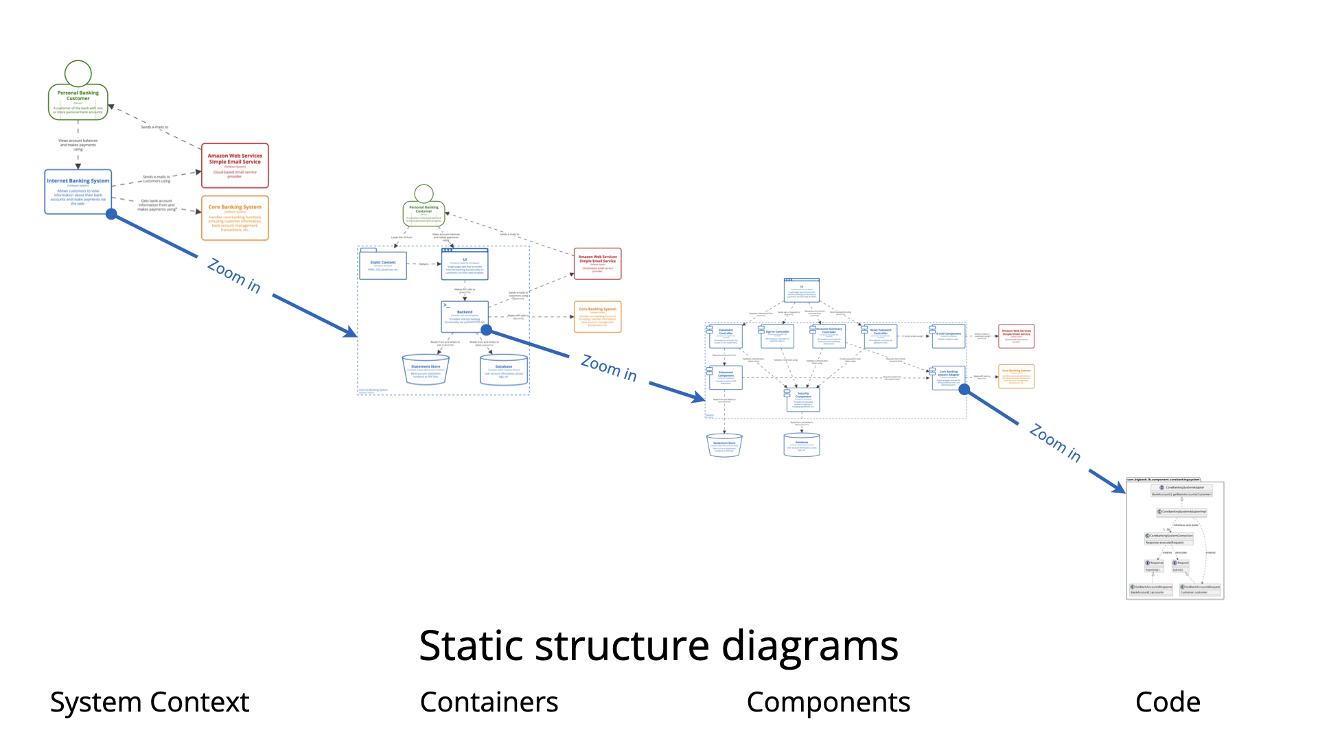
The C4 model is a technique designed to visualize software architecture at different levels of abstraction. Its primary purpose is to help development teams communicate design decisions effectively during planning and documentation phases. It breaks systems down into four manageable levels:
UML Component Diagrams are purely structural. They are used to model software modularity and define dependencies. These diagrams illustrate how various software components wire together to form a larger system, providing the necessary roadmap for the static architecture.
In contrast, UML State Machine Diagrams serve a behavioral purpose. They model an entity’s behavior based on its current and past states, detailing how it responds to specific events through transitions and actions. This is crucial for understanding the lifecycle of an object within the system.
While both diagrams are essential for comprehensive documentation, their fundamental differences lie in the dichotomy between structure and behavior.
| Feature | UML Component Diagram | Supplementary State Diagram |
|---|---|---|
| Primary Type | Structural (Static) | Behavioral (Dynamic) |
| Focus of Analysis | Modularity and Dependencies | Logic, Transitions, and Event Responses |
| Perspective in C4 | Shows the “What” of Level 3 (Components) | Shows the “How” of operational logic within components |
| Goal | To map connection points and architecture | To map lifecycle and decision paths |
The C4 model excels at visualizing static hierarchy, yet it often lacks the granularity required to explain complex operational logic. Integrating supplementary state diagrams addresses several critical needs in system design.
Systems with critical state-dependent behavior cannot be fully understood through static diagrams alone. For example, hardware integrations like 3D printers or automated toll systems require state diagrams to map every possible transition. This ensures that the system handles states like Heating, Printing, and Error correctly, avoiding costly design errors.
At the Component (Level 3) and Code (Level 4) stages, a gap often exists between the architectural definition and the actual code. A state diagram acts as a bridge, explaining the internal lifecycle of a component defined in the C4 model. This visualizes the “logic” that the code must implement.
Using state diagrams alongside C4 allows developers to identify missing or undefined behavioral paths early in the design phase. While a component diagram might show that a Payment Processor is connected to a Bank API, a state diagram reveals what happens if the payment hangs in an Authorized state without transitioning to Captured.
Modern tools are changing how these diagrams are generated. The Visual Paradigm platform utilizes generative AI to streamline the creation of both structural and behavioral models, reducing the manual effort required for documentation.
To visualize how these concepts function in the real world, consider the following scenarios:
A car park booking system is best visualized using C4 levels. The Context level shows the user; Containers show the web app and database; and Components show the booking manager. However, within that system, an “Automated Toll Component” requires a supplementary state diagram. This diagram models the specific transition from Idle to ProcessingPayment, and finally to GateOpen upon success.
Similarly, a 3D Printer can be modeled structurally as a component connected to a PC. However, its operational logic is entirely state-dependent. A supplementary state machine diagram captures the nuances of heating elements, verifying safety sensors, and managing print jobs, which is information a structural diagram simply cannot convey.
The following articles and resources provide detailed information on using AI-powered tools to create and refine C4 models and UML component diagrams within the Visual Paradigm platform:
Major Upgrade to AI UML Component Diagram Generation in Visual Paradigm AI Chatbot: The Visual Paradigm AI Chatbot now offers advanced capabilities for generating UML component diagrams directly from natural language prompts.
AI-Powered Component Diagrams with Visual Paradigm Chatbot: This tool simplifies the creation of component diagrams by transforming natural language descriptions into precise, ready-to-use models.
Comprehensive Tutorial: Generating and Modifying C4 Component Diagrams with Visual Paradigm AI Chatbot: This tutorial demonstrates how to use the AI-powered chatbot to generate and refine C4 component diagrams for specific use cases like a car park booking system.
AI-Powered C4 Diagram Generator – Visual Paradigm AI: The AI-powered generator supports documentation for the four core levels of the C4 model, including context, container, component, and deployment views.
The Ultimate Guide to C4-PlantUML Studio: Revolutionizing Software Architecture Design: This guide explores how C4-PlantUML Studio combines AI-driven automation with PlantUML’s flexibility to streamline software architecture design.
A Comprehensive Guide to Visual Paradigm’s AI-Powered C4 PlantUML Studio: This guide describes how the studio transforms natural language input into accurate and layered C4 diagrams for complex system visualization.
C4 Model AI Generator: Automate Context: The Visual Paradigm AI Chatbot uses conversational prompts to automate the full lifecycle of C4 modeling for development teams.
AI-Generated UML Component Diagrams: Artificial intelligence assistance enables the accurate and efficient creation of UML component diagrams for modern software design.
Why Every Team Needs an AI Diagram Maker for Faster Project Kickoff: This article explains how AI-powered modeling tools accelerate project initiation by automating the creation of UML and component diagrams.
AI Diagram Generator: Complete C4 Model Support: This release introduces an AI-powered generator that enables the automatic creation of diagrams based on the C4 model.
Visual Paradigm Full C4 Model Support Release: Visual Paradigm provides full support for creating and managing C4 architecture diagrams at multiple abstraction levels using artificial intelligence.
UML Component Diagram Tutorial and Tool – Visual Paradigm: This resource provides an interactive guide for using AI tools to model system architecture and various component relationships.