 Visual Paradigm Desktop |
  Visual Paradigm Online


UML class diagrams are foundational tools in object-oriented software engineering, providing a clear, visual representation of a system’s static structure. These diagrams define the classes, attributes, operations, and relationships between objects, forming the blueprint for both high-level domain modeling and detailed technical architecture. As software systems grow in complexity, understanding and effectively leveraging UML class diagrams becomes increasingly critical for architects, developers, and product owners.
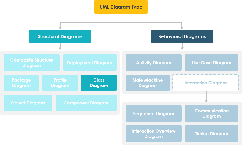
UML (Unified Modeling Language) class diagrams are structural diagrams that illustrate the static aspects of a system. They depict how classes relate to one another through associations, aggregations, compositions, and inheritance, enabling teams to model domain logic, data structures, and system dependencies with precision and clarity.
Every UML class diagram is built on a few core elements:
These components allow architects to define not only what data exists in the system but also how it is structured and manipulated, supporting encapsulation, modularity, and maintainability.
The relationships in a class diagram define how classes interact and depend on one another. The most common relationships include: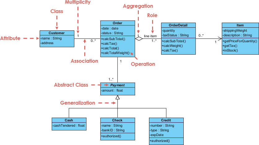
These relationships are not just visual—they form the logical foundation of system behavior, helping to identify dependencies, reduce redundancy, and ensure consistency across the software design.
Traditionally, creating UML class diagrams involved a labor-intensive, manual process. Architects had to extract entities from documentation, analyze requirements, and manually sketch out class relationships—often leading to errors, inconsistencies, or missed dependencies.
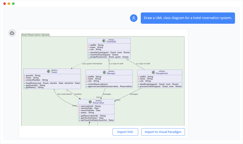
Modern AI-powered modeling tools, such as the Visual Paradigm AI Chatbot, are transforming this workflow. Instead of manually drafting diagrams, engineers can interact with an intelligent modeling partner using natural language.
Using AI Textual Analysis, the tool automatically identifies domain classes, attributes, and relationships from unstructured text inputs—such as user stories or business requirements. For instance, entering the sentence: ‘A customer places an order for a product, which is stored in the system with a date and total amount’ would instantly generate a class diagram with classes like ‘Customer’, ‘Order’, ‘Product’, and appropriate attributes and relationships.
This approach enables rapid prototyping, reduces cognitive load, and ensures that models reflect real-world business logic accurately and consistently.
One of the most valuable aspects of UML class diagrams is their role as a bridge between design and implementation. Through forward and reverse engineering, teams can move seamlessly between visual models and source code.
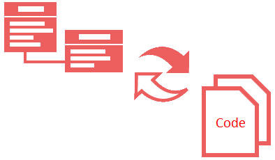
Modern modeling platforms support instant code generation in multiple programming languages, including Java, C#, and C++. Developers can generate fully functional class definitions, constructors, methods, and even method signatures directly from the diagram.
For applications with database persistence requirements, these tools can generate ORM (Object-Relational Mapping) code compatible with frameworks like Hibernate or JPA. This ensures that the class model is synchronized with the database schema, reducing manual mapping errors and accelerating development cycles.
For example:
| Feature | Traditional Approach | AI-Powered Approach |
|---|---|---|
| Class Creation | Manual entity identification from documents | Automated from natural language prompts |
| Relationship Mapping | Time-consuming manual drawing | Auto-detected via AI textual analysis |
| Code Generation | Manual translation or scripting | Instant generation in multiple languages |
| ORM Mapping | Manual table-to-class mapping | Auto-generated with database schema alignment |
This automation significantly reduces development time and increases accuracy, especially in large-scale enterprise systems where domain complexity is high.
While UML class diagrams represent abstract, static structures and define the rules governing how classes interact, object diagrams depict specific instances of classes and their relationships at a particular point in time.
Object diagrams are valuable for validating design decisions against runtime scenarios. For instance, an object diagram may show a specific ‘Customer’ object with an ‘Order’ instance and a ‘Product’ being purchased. This helps architects verify that the class model is not only logically sound but also functionally valid in real-world execution.
The key differences are summarized below:
| Aspect | Class Diagram | Object Diagram |
|---|---|---|
| Scope | Abstract, system-wide rules | Concrete, runtime instances |
| Use Case | Design, modeling, architecture | Validation, behavior verification |
| Relationships | Fixed, defined by inheritance | Dynamic, specific to instance state |
| Time Dependency | Static (time-independent) | Dynamic (time-bound) |
Together, class and object diagrams provide a complete picture: the class diagram defines the system’s structure, while the object diagram demonstrates how that structure behaves in practice.
To maximize effectiveness, follow these best practices:
The integration of AI into modeling workflows is not a temporary trend—it represents a fundamental shift in how software systems are designed and developed. AI-powered tools are no longer just assistants; they are intelligent co-pilots that understand context, extract meaning from natural language, and generate accurate, production-ready models.
As AI technologies evolve, UML class diagrams will continue to serve as the central nexus between human intent and machine execution. Future iterations may include:
By embracing these tools, software teams can focus on strategic design decisions while leaving the repetitive, error-prone tasks of modeling to intelligent systems.
UML class diagrams remain one of the most powerful tools in software engineering, providing a clear, structured way to model system architecture. With traditional modeling practices being replaced by AI-powered solutions like those in Visual Paradigm, the process is becoming faster, more accurate, and accessible to non-experts.
Whether you’re designing a simple e-commerce system or a complex enterprise application, understanding UML class diagrams—and leveraging modern AI capabilities—provides a significant advantage in achieving better software quality, faster delivery, and improved team collaboration.
AI-Assisted UML Class Diagram Generator – Visual Paradigm: This tool allows users to generate UML class diagrams with AI-powered suggestions, validation, PlantUML export, and design analysis.
AI-Powered UML Class Diagram Generator by Visual Paradigm: Users can generate accurate UML class diagrams from natural language descriptions using AI-assisted automation.
Interactive AI Chat for UML Class Diagram Generation: This conversational AI interface enables the generation of UML class diagrams through natural language interaction directly in a web browser.
AI-Assisted UML Class Diagram Generator – Visual Paradigm AI Toolbox: This AI-powered tool generates UML class diagrams from text descriptions while requiring minimal manual input.
From Problem Description to Class Diagram: AI-Powered Textual Analysis: Visual Paradigm’s AI-powered textual analysis converts natural language problem descriptions into accurate class diagrams.
Identifying Domain Classes Using AI Textual Analysis in Visual Paradigm: AI tools in Visual Paradigm automatically identify domain classes from unstructured text to streamline the software modeling process.