 Visual Paradigm Desktop |
  Visual Paradigm Online
In the world of software engineering and system design, understanding how components interact over time is as crucial as defining what they do. Enter Sequence Diagrams — a powerful tool in the Unified Modeling Language (UML) arsenal that visualizes the dynamic behavior of systems by illustrating the chronological flow of messages between objects or actors.
Whether you’re designing a simple login process or modeling a complex enterprise workflow, sequence diagrams offer a clear, intuitive way to map out interactions, validate logic, and communicate with stakeholders across technical and non-technical teams.
This comprehensive guide dives deep into the purpose, structure, best practices, and advanced features of UML sequence diagrams — and reveals how modern AI-powered tools like Visual Paradigm are revolutionizing their creation.
A sequence diagram is a type of interaction diagram in UML that captures the temporal sequence of interactions between objects or actors within a system. It emphasizes:
The order of events (time flows downward).
The lifelines of participating entities.
The messages exchanged — including synchronous, asynchronous, return, and self-messages.
The activation periods when objects are actively processing.
📌 Think of it as a storyboard for software behavior: who does what, when, and in what order.
Sequence diagrams serve multiple critical roles in system design and development:
Model use-case scenarios: Show how a system behaves in response to user actions (e.g., booking a hotel room).
Detail object collaborations: Illustrate how objects work together to fulfill a specific operation.
Document system behavior: Serve as blueprints for developers, testers, and product owners.
Support UX wireframing and testing: Identify potential bottlenecks, race conditions, or missing steps before coding.
| Benefit | Explanation |
|---|---|
| Language-Neutral | Understandable by non-developers — ideal for stakeholder communication. |
| Promotes Collaboration | Teams can co-create diagrams during brainstorming sessions. |
| High-Level Abstraction | Focus on logic, not implementation details — perfect for planning. |
| Test-Driven Design Support | Helps identify edge cases and failure paths early. |
| Traceable to Use Cases | Easily linked to use case diagrams for full behavioral modeling. |
💡 They’re not code — they’re collaboration tools that bridge design and implementation.
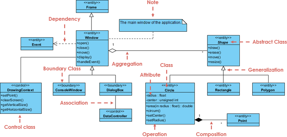
Sequence diagrams follow a strict layout: participants are arranged horizontally, and time flows vertically (top to bottom). Here’s a breakdown of essential components:
An external entity interacting with the system.
Represented as a stick figure (e.g., Customer, Payment Gateway).
Can represent users, hardware, or other systems.
A dashed vertical line extending from a participant’s name.
Represents the lifetime of that object or actor during the interaction.
A thin rectangle on a lifeline.
Shows when an object is actively executing a method or operation.
Activation begins when a message is received and ends when processing is complete.
⏱️ Note: Activation height does not represent actual time duration — it’s symbolic.
Messages define interactions. Their types determine how control flows.
| Message Type | Symbol | Description |
|---|---|---|
| Call (Synchronous) | Solid arrow, filled arrowhead (→) |
Invokes a method; waits for return. |
| Return (Response) | Dashed arrow, open arrowhead (⤬) |
Returns control/data after processing. |
| Asynchronous | Solid arrow, open arrowhead (→) |
Sends a message without waiting; continues execution. |
| Self Message | Arrow to same lifeline | Internal method call (e.g., validate() within Customer). |
| Recursive Message | Self-message starting above current activation | Method calls itself — activation overlaps. |
| Create Message | Dashed arrow with «create» stereotype |
Instantiates a new object. |
| Destroy Message | Arrow ending in an “X” (→X) |
Terminates the lifeline (object destroyed). |
| Duration Message | Horizontal bar with label | Shows time elapsed on a lifeline. |
A dog-eared rectangle used for annotations.
No semantic impact — purely for explanation (e.g., “Only if available”).
🎯 Pro Tip: Always label messages clearly — avoid vague terms like “send data.” Instead, use “send booking confirmation email” or “request payment status.”
Follow this structured process to build accurate and readable sequence diagrams:
List all actors and objects involved in the interaction (e.g., Customer, Reservation Window, Hotel System, Payment Gateway).
Arrange them left to right in the order they first participate.
Decide whether the diagram represents:
A generic scenario (all possible paths), or
An instance-specific path (one concrete execution flow).
Use instance-specific diagrams for clarity and focus.
Start from the top and draw messages downward in chronological order.
Draw lifelines for each participant.
Add activations where objects are processing.
Use appropriate message types (call, return, async, etc.).
Use combined fragments to express complex logic like conditions, loops, or parallelism.
See the next section for full details.
Add notes to clarify decisions or assumptions (e.g., “Only if room is available”).
Include guard conditions on messages (e.g., [payment approved]).
Check that:
All lifelines are properly activated.
Messages are logically ordered.
The diagram matches the intended use case or operation.
No missing return messages or unbalanced activations.
✅ Best Practice: Have a peer review — sequence diagrams are meant to be collaborative.
Introduced in UML 2.0, combined fragments are rectangular boxes that group parts of the interaction to express complex control logic.
They are defined by a keyword in the top-left corner and contain one or more interaction operands.
| Fragment | Use Case | Example |
|---|---|---|
alt |
Alternatives (if/else) | “If payment successful → confirm booking; else → show error” |
opt |
Optional (if condition true) | “If user has loyalty points → apply discount” |
par |
Parallel execution | “Check availability & verify payment” (both run simultaneously) |
loop |
Repetition | “While rooms exist → search next room” |
break |
Exit from enclosing fragment | “If timeout → break out of loop” |
neg |
Negative scenario | “If no response within 10s → cancel request” |
ref |
Reference to another interaction | “Call validateUser() from login sequence” |
sd |
Frame entire diagram | Used for structuring large diagrams |
🔁 Nested Fragments: You can nest fragments (e.g.,
loopinsidealt) for highly complex behaviors.
✨ Tip: Use
parandlooptogether to model concurrent iterations (e.g., parallel search across multiple servers).
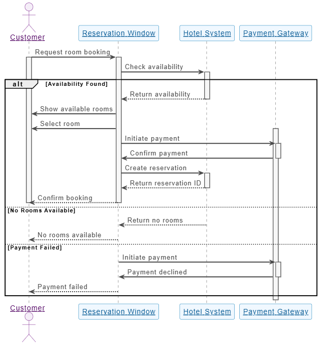
Customer → Reservation Window: Request room booking
Reservation Window → Hotel System: Check availability
Hotel System → Reservation Window: Return availability
Reservation Window → Customer: Show available rooms
Customer → Reservation Window: Select room
Reservation Window → Payment Gateway: Initiate payment
Payment Gateway → Reservation Window: Confirm payment
Reservation Window → Hotel System: Create reservation
Hotel System → Reservation Window: Return reservation ID
Reservation Window → Customer: Confirm booking
Fragments used: alt for payment success/failure, loop for searching rooms.
Activation: Hotel System activates during availability check.
Create message: Create reservation — new Reservation object is instantiated.

alt [Payment Successful]
    Payment Gateway → Reservation Window: Confirm payment
else [Payment Failed]
    Payment Gateway → Reservation Window: Reject payment
    Reservation Window → Customer: Show error message
end
This clearly separates two paths based on real-time decisions.
| Practice | Why It Matters |
|---|---|
| Keep diagrams focused | One scenario per diagram — avoid clutter. |
| Order lifelines logically | First participant to act appears leftmost. |
| Use fragments wisely | Avoid overusing alt, loop, par — keep it readable. |
| Link to use cases | Ensure traceability from use case → sequence diagram. |
| Review collaboratively | Involve developers, testers, and UX designers. |
| Pitfall | Risk |
|---|---|
| Using vertical space as literal time | Activations should reflect processing, not duration. |
| Mixing static and dynamic models | Don’t combine class diagrams with sequence diagrams. |
| Too many messages | Overload the diagram — aim for high-level clarity. |
| Ignoring return messages | Missing returns can imply infinite waits or broken flows. |
| No guard conditions | Unclear decision logic leads to ambiguity. |
🚫 Golden Rule: If you can’t explain the diagram in 60 seconds, simplify it.
Traditional sequence diagram creation often involves:
Starting from a blank canvas.
Manually placing lifelines and messages.
Iterating through multiple drafts.
Enter Visual Paradigm’s AI-powered ecosystem — a next-generation platform that turns sequence diagrams into a conversational, intelligent design process.
| Platform | Function |
|---|---|
| VP Desktop | Full-featured desktop IDE for deep editing, code generation, and version control. |
| OpenDocs | Smart documentation tool to embed and link diagrams into reports, wikis, or Confluence pages. |
| AI Visual Modeling Chatbot | Describe your scenario in plain English — get a professional diagram instantly. |
| Web Apps | Guided, step-by-step tools for structured modeling (ideal for beginners). |
Input: Natural language prompt like:
“Create a sequence diagram for a hotel reservation system with Customer, Reservation Window, and Hotel System. Include an alt fragment for payment success vs. failure.”
Output: Instantly generates a clean, UML-compliant sequence diagram.
Refinement: You can continue the conversation:
“Make the payment message asynchronous.”
“Add a loop to search for available rooms.”
✨ Result: A fully functional, refined diagram in under 60 seconds.
Automatically improves diagrams by:
Fixing inconsistent message types.
Suggesting optimal fragment usage.
Enforcing UML compliance and best practices.
Seamlessly links to:
Use Case Diagrams → Trace back to the original scenario.
Activity Diagrams → Model control flow.
Class Diagrams → Define object types and attributes.
State Machine Diagrams → Show object lifecycle.
🔗 End-to-End Traceability: Every diagram is connected — changes propagate automatically.
Start with AI Chatbot
→ Describe your use case in natural language.
Refine via Conversation
→ “Add a loop for room search”
→ “Make the payment message asynchronous”
Switch to Web Apps
→ Get guided, step-by-step assistance for complex logic.
Move to VP Desktop
→ Fine-tune layout, export to PNG/PDF, generate code, or integrate with version control.
Embed in OpenDocs
→ Drop the diagram into reports, wikis, or presentations — it stays editable and linked.
| Feature | Traditional Approach | Visual Paradigm AI Ecosystem |
|---|---|---|
| Initial Setup | Manual drawing, time-consuming | Instant generation from text |
| Learning Curve | Steep for beginners | Low — intuitive chat interface |
| Iteration Speed | Slow, error-prone | Fast, conversational refinements |
| Team Collaboration | Hard to coordinate | Real-time, shared workspace |
| Traceability | Manual linking | Automatic, bi-directional links |
| Cross-Platform Use | Limited | Cloud + Desktop + Docs + Web |
💬 Bottom Line: The AI ecosystem eliminates the blank page problem, accelerates prototyping, and ensures professional quality — even for non-experts.
Sequence diagrams are no longer just static diagrams — they are living, collaborative, and intelligent artifacts in modern software development.
With Visual Paradigm’s AI ecosystem, creating a sequence diagram has evolved from a manual, error-prone task into a conversational, guided, and traceable process.
Whether you’re:
A product owner explaining a feature to a dev team,
A developer planning a complex interaction,
Or a tester identifying edge cases,
👉 Start with the AI chatbot for speed,
👉 Refine with guided tools,
👉 Finalize in VP Desktop for production use,
👉 Embed in OpenDocs for documentation.
✅ Use sequence diagrams to visualize dynamic behavior.
✅ Keep them focused, readable, and linked to use cases.
✅ Leverage combined fragments for complex logic.
✅ Use AI tools to generate, refine, and maintain diagrams efficiently.
✅ Integrate with other UML diagrams for full lifecycle modeling.
🎯 Pro Tip: The best sequence diagrams are not the most detailed — they’re the ones that communicate clearly, quickly, and correctly.
Try the Visual Paradigm AI Visual Modeling Chatbot today:
👉 https://www.visual-paradigm.com
Start with a simple prompt like:
“Create a sequence diagram for a user login process with username/password, authentication service, and session manager.”
In seconds, you’ll have a professional-grade diagram — and a new way to think about system design.
Transform your workflow. Design with intelligence. Build with clarity.
Welcome to the future of UML modeling — powered by AI. 🚀
Visual Paradigm – AI-Powered UML Sequence Diagrams: This resource explains how to generate professional UML sequence diagrams directly from text prompts using an advanced AI modeling suite.
Mastering Sequence Diagrams with Visual Paradigm: AI Chatbot Tutorial: This beginner-friendly tutorial uses a real-world e-commerce chatbot case study to teach users how to build sequence diagrams using an AI assistant.
AI-Powered Sequence Diagram Refinement Tool | Visual Paradigm: This article discusses how AI can enhance software design by automatically improving and optimizing sequence diagrams with intelligent suggestions.
Comprehensive Tutorial: Using the AI Sequence Diagram Refinement Tool: A step-by-step guide on leveraging specialized AI features to improve the accuracy, clarity, and consistency of sequence diagrams.
Simplify Complex Workflows with Visual Paradigm AI Sequence Diagram Tool: This article explores how AI-enhanced tools simplify the process of modeling complex system interactions and technical workflows.
Beginner’s Tutorial: Create Your First Professional Sequence Diagram in Minutes: A hands-on guide for new users to generate high-quality sequence diagrams quickly using a conversational AI chatbot.
From Simple to Sophisticated: AI-Powered Sequence Diagram Refinement Tool: This resource explains how AI features can evolve basic diagram drafts into sophisticated, accurate models with minimal user effort.
Refining Sequence Diagrams with AI: A Smarter Way to Design Systems: This article details how AI-driven intelligence provides a more efficient approach to system design through automated diagram refinement.
AI Sequence Diagram Example: Video Streaming Playback Initiation: A case study showing an AI chatbot acting as a modeling partner to interpret intent and refine the logic for starting playback on a streaming platform in real time.
AI-Powered Sequence Diagram Refinement from Use Case Descriptions: This guide explores how AI transforms unstructured use-case descriptions into precise, professional sequence diagrams automatically.